Pallet rack

a pallet rack and pallet technology, applied in the field of pallet racks, can solve the problems of increasing the time and labor associated with assembling the pallet rack, the connection structure used to connect the frames to the upper and lower pallets is in general very complex and requires many individual parts, and the standard warehouse-type pallet cannot be incorporated into the pallet rack, so as to reduce the number of different parts required, simplify the assembly of the pallet rack, and ensure the effect of stability

Inactive Publication Date: 2005-09-29
TYLER JOSH
View PDF19 Cites 5 Cited by
  • Summary
  • Abstract
  • Description
  • Claims
  • Application Information

AI Technical Summary

Benefits of technology

[0013] The present invention overcomes the aforementioned disadvantages of prior pallet racks in numerous ways. The present invention simplifies assembly of a pallet rack, reduces the number of different parts required in a pallet rack, provides greater support and stability for an upper pallet supported on a lower pallet of a pallet rack, provides stabilization for objects supported on upper and lower pallets of a pallet rack including objects supported in vertically stacked rows on the upper and lower pallets of the pallet rack, and allows conventional or standard pallets to be used as the upper and lower pallets in a pallet rack without requiring substantial modifications to the conventional pallets. The present invention simplifies the frame structure used to support an upper pallet in vertical spaced relation on a lower pallet and simplifies the connecting structure used to connect the upper pallet to the frame structure. The present invention utilizes connectors to connect the upper pallet in supporting relation on the frame, and further allows the same type of connecters to be used to attach the frame to the lower pallet. The upper pallet may be provided with a frame of the same type as the lower pallet, and shelves may be supported on either or both of the frames in vertical spaced relation allowing objects to be arranged on either or both of the pallets in vertically stacked rows.
[0014] Some of the advantages of the present invention are that the time and labor needed to assemble the pallet rack is reduced; the same type of frame may be used with the upper and lower pallets of the pallet rack for greater consistency and uniformity of parts; attachment of the upper pallet on the frame of the lower pallet and detachment of the upper pallet from the frame of the lower pallet are both facilitated; various objects may be loaded onto the lower pallet and / or the upper pallet of the pallet rack; the pallet rack may be transported or moved from place to place in a loaded or unloaded condition; a pallet rack having objects loaded thereon may be placed on a truck or other carrier for transport from one destination to another; objects arranged in vertically stacked rows on the lower and / or upper pallets are prevented from toppling; stabilizing bars are provided along each side of the pallet; some of the stabilizing bars are removable from the frames to provide access to objects on the pallets; some of the stabilizing bars are permanently affixed to the frames to provide structural strength and rigidity to the frames and to constrain objects on the pallets even when the removable stabilizing bars are removed; the pallet rack facilitates the application of packing material around objects disposed on the pallets including around objects disposed on the pallets in vertically stacked rows; the pallet rack facilitates the removal of packing material from objects disposed on the pallets without requiring that the objects, including those disposed on the pallets in vertically stacked rows, be moved or rearranged; the pallet rack is particularly suitable for holding fragile objects and for protecting fragile objects against damage when the pallet rack is transported or moved with the objects loaded thereon; and the pallet rack presents an attractive appearance conducive to use as a point of sale display.

Problems solved by technology

Some prior pallet racks require that the lower pallet and / or the upper pallet be customized such that conventional or standard warehouse-type pallets cannot be incorporated in the pallet racks.
The frames used in prior pallet racks to support an upper pallet on top of a lower pallet and the connecting structure used to connect the frames to the upper and lower pallets are in general very complex and require many individual parts.
The structural complexity and the large number of individual parts required by many prior pallet racks greatly increase the time and labor associated with assembling the pallet racks and detaching the upper pallets from the lower pallets.
The structural complexity and the number of parts associated with prior pallet racks also detract from their aesthetic appearance.
Prior pallet racks are also lacking in consistency and uniformity of parts in that the same connecting structures used to connect the frame to the upper pallets cannot also be used to connect the frame to the lower pallets.
Many prior pallet racks are not designed to provide adequate stabilization for objects arranged in vertically stacked rows on the pallet while also allowing the pallets racks to be transportable.
Rather, many prior pallet racks cannot be transported in a loaded condition without jeopardizing the safety and integrity of the objects carried on the pallets.
The frames and connecting structures used in many prior pallet racks provide obstructions which interfere with the application and removal of packing material to objects loaded on the upper and lower pallets of the pallet rack.

Method used


Image

  • Pallet rack
  • Pallet rack
  • Pallet rack

Examples


Embodiment Construction

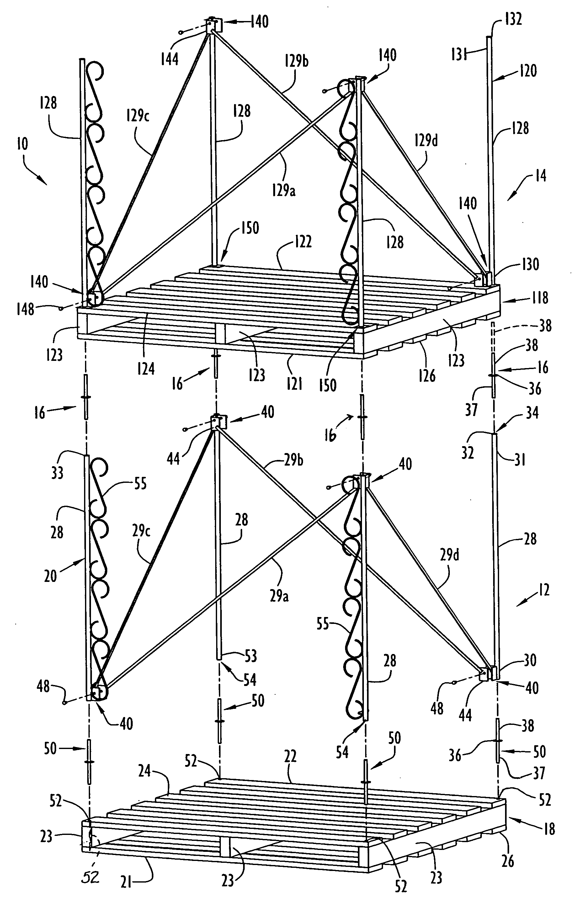
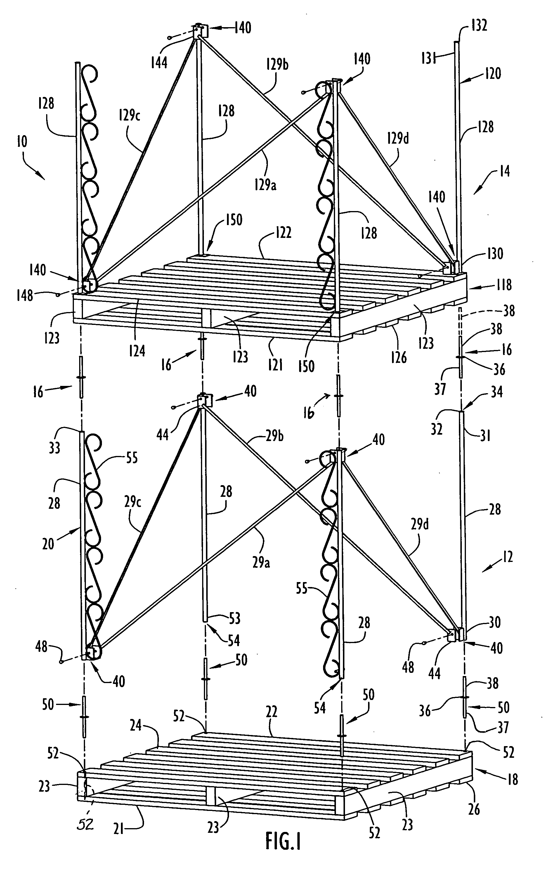
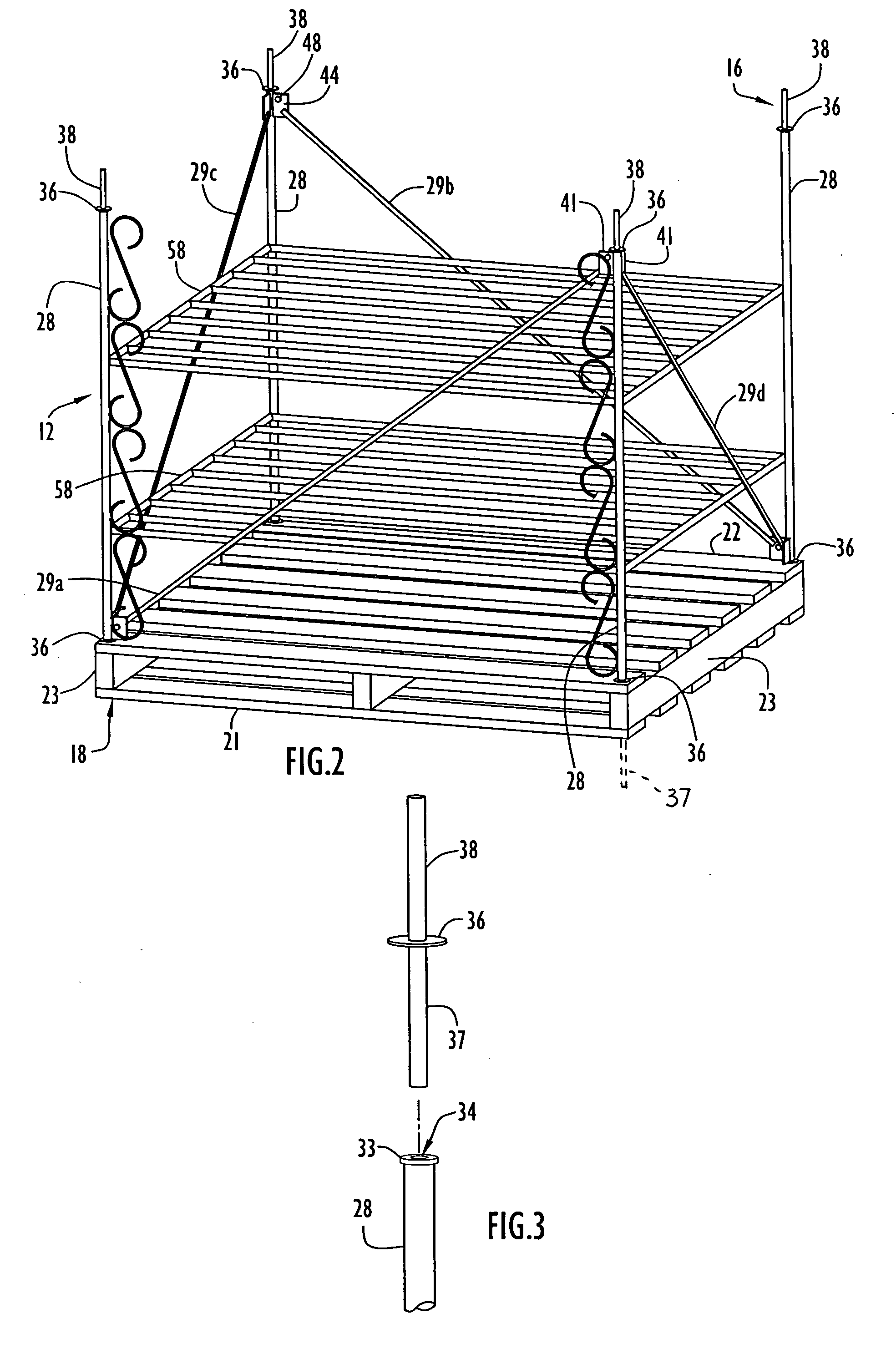
[0029] A pallet rack 10 according to the present invention is illustrated in FIG. 1 in an unassembled condition. The pallet rack 10 comprises a lower pallet unit 12, an upper pallet unit 14 and a plurality of connectors 16 for connecting the upper pallet unit 14 in supporting relation on the lower pallet unit 12. The lower pallet unit 12 comprises a lower pallet 18 and a frame 20 attached to the lower pallet 18. The lower pallet 18 has a lower surface 21 for being supported on the ground, floor or other support surface and an upper surface 22 on which one or more various objects may be supported. The lower pallet 18 may have a perimeter or footprint of square or nearly square configuration defining four corners. The lower pallet 18 may be a conventional warehouse-type pallet comprising a plurality of stringers 23 and an upper deck 24 secured to and supported on top sides of the stringers 23. The stringers 23 may be boards having a length, width and thickness, with the width of the s...


PUM


Abstract

A pallet rack is characterized by a lower pallet unit and an upper pallet unit supported on the lower pallet unit. The lower pallet unit includes a lower pallet and plurality of posts extending upwardly from the lower pallet. The posts have lower portions secured to the lower pallet and have upper portions. The upper portions have longitudinal passages terminating at upper ends circumscribing entry openings into the passages. The upper pallet unit includes an upper pallet having a lower surface and a plurality of bores in the upper pallet with entry openings along the lower surface in respective longitudinal alignment with the passages. Connectors connect the upper pallet to the posts and have upper extensions respectively received in the bores of the upper pallet, lower extensions respectively received in the passages of the posts, and flanges disposed between the lower surface of the upper pallet and the upper ends of the passages.

Description

BACKGROUND OF THE INVENTION [0001] 1. Field of the Invention [0002] The present invention relates generally to pallet racks and, more particularly, to pallet racks having a lower pallet unit and an upper pallet unit supported on top of the lower pallet unit via connectors. [0003] 2. Discussion of the Related Art [0004] Pallets are used in various situations to support many various types of objects. A conventional warehouse-type pallet typically includes a plurality of stringers extending longitudinally in spaced parallel relation and an upper deck secured to top sides of the stringers to provide a horizontal platform or support surface for supporting one or more objects. Commonly the stringers are wooden boards which have a length, width and thickness, and are positioned with their width oriented vertically or perpendicular to the horizontal surface of the upper deck. The upper deck is ordinarily made up of a plurality of wooden boards extending longitudinally in a direction transve...

Claims


Application Information

Patent Timeline
Patent Type & Authority Applications(United States)
IPC IPC(8): A47B43/00B65D19/38
CPCB65D19/385B65D2519/00024B65D2519/00029B65D2519/00064B65D2519/0082B65D2519/00129B65D2519/00164B65D2519/00233B65D2519/00273B65D2519/00099
Inventor TYLER, JOSH
Owner TYLER JOSH
Why Eureka
Try Eureka