Method of sealing machine components

a technology of sealing machine components and components, applied in the direction of mechanical equipment, valves, basic electric elements, etc., can solve the problems that no technology has been applied to the purpose of sealing machine components, and achieve the effects of reducing energy consumption, adequate sealing, and reducing friction and deformation losses

Inactive Publication Date: 2005-09-29
POPADIUC PETER OVIDIU
View PDF7 Cites 5 Cited by
  • Summary
  • Abstract
  • Description
  • Claims
  • Application Information

AI Technical Summary

Benefits of technology

[0004] A first objective of this invention is to define a sealing method that virtually eliminates most friction and deformation losses during a sealing process. More particularly, this method consists of using electroactive polymers capable of ensuring adequate sealing, and of minimizing the energy consumption.

Problems solved by technology

For example, in the case of a butterfly valve, a bubble tight sealing between the disc and valve's body may consist of interference between the disc's circumference and a soft material on the valve's body.
In the past, several devices using electroactive materials where invented, but none were developed for the purpose of sealing machine components.

Method used


Image

  • Method of sealing machine components
  • Method of sealing machine components
  • Method of sealing machine components

Examples


Embodiment Construction

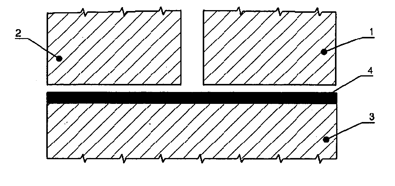
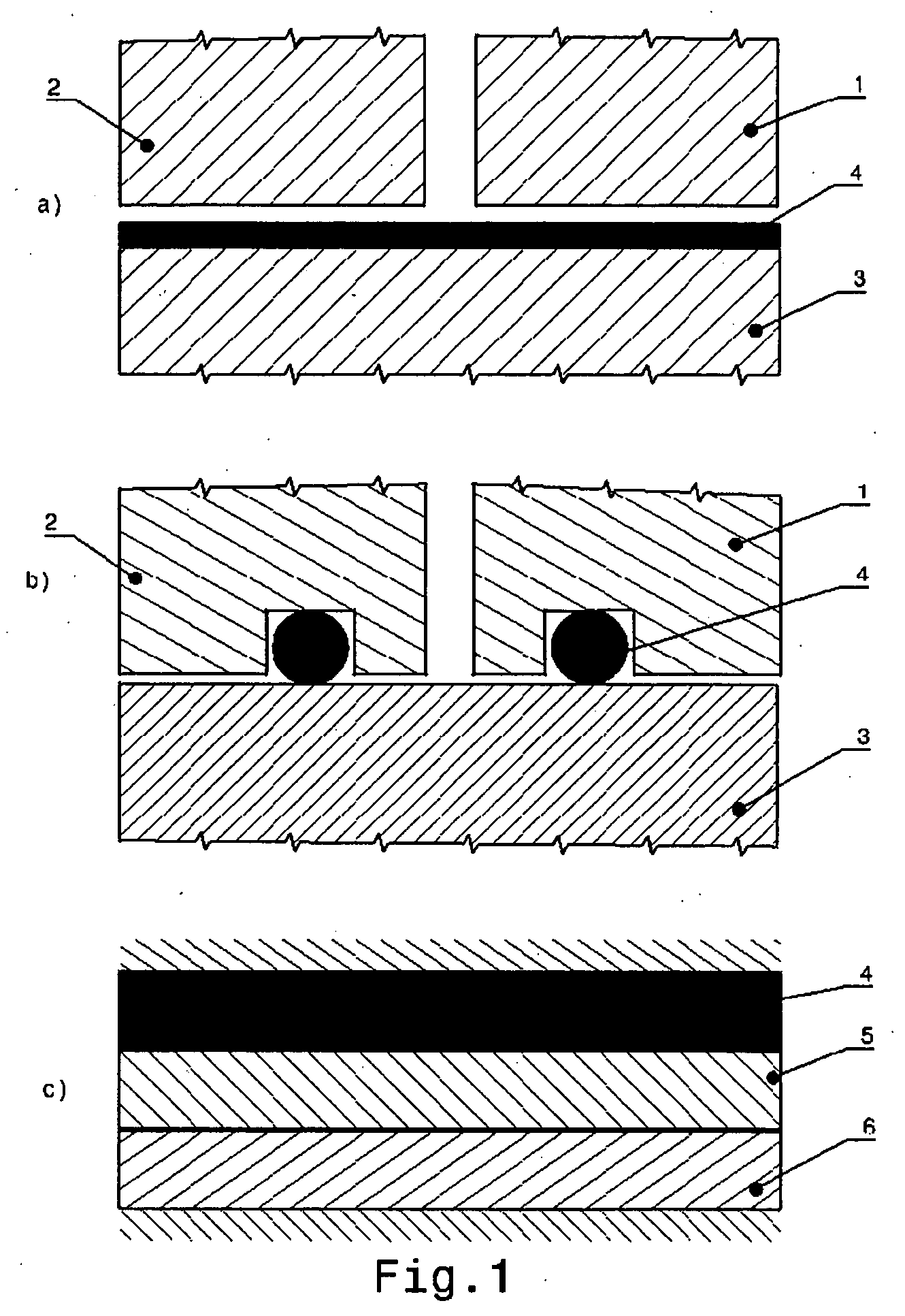
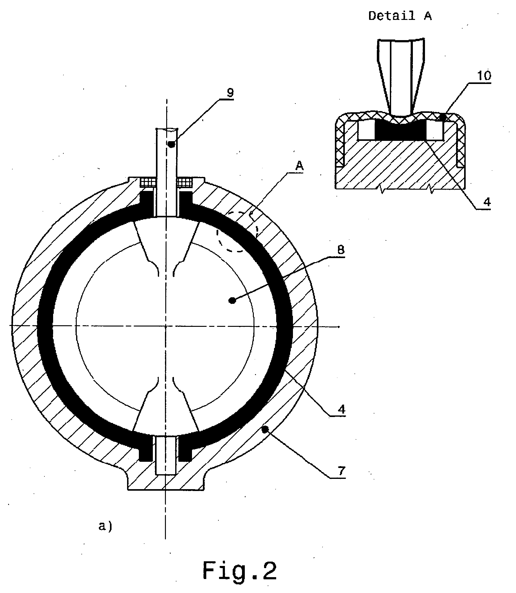
[0022] FIGS. 2(a, b, c) illustrate the basic elements of the preferred embodiment of this invention. A butterfly valve has a circumferential groove machined into its body 7 around the disc 8 circumference when closed. On this groove there is installed an annular band 4 made out of an electroactive polymer which may or may not be covered by a protective elastic membrane 10.

[0023] When the valve is closed and a seal is required, the voltage is removed from the electro-active polymer strip 4. These electroactive polymers then relax and interfere with the disc 8 around the disc circumference. When the valve needs to open, a voltage is applied to the electro-active polymer actuator 4 that compresses and therefore allows disc 8 to move freely. The valve actuator then rotates disc 8 via torque transmission through shaft 9. The driver of the electro-active polymer actuator can turn off the circuit in order to stop disc 8 in a desired intermediate open position. A mirror function of this me...


PUM


Abstract

This application relates to a method of sealing machine components using electroactive materials that can be energized through a separate electric circuit or electric field in order to eliminate most friction and deformation losses during a sealing process.

Description

FIELD OF THE INVENTION [0001] This invention relates to a method of sealing machine components using electroactive materials. These materials are generally polymers and have the property of changing their geometry and dimensions when subjected to a voltage or electrical field. BACKGROUND OF THE INVENTION [0002] Sealing concepts are typically based on compression and interference of some sealing surfaces or deformation of a generally elastic material placed between them in order to perform sealing. Movable machine components sealing requires additional energy consumption and oversized actuators in order to overcome the frictions that accompany sealing processes. For example, in the case of a butterfly valve, a bubble tight sealing between the disc and valve's body may consist of interference between the disc's circumference and a soft material on the valve's body. Material interference drives supplementary energy consumption generally provided by oversized actuators that are capable ...

Claims


Application Information

Patent Timeline
Patent Type & Authority Applications(United States)
IPC IPC(8): F16K1/226F16K31/02
CPCF16K1/226
Inventor POPADIUC, PETER OVIDIU
Owner POPADIUC PETER OVIDIU
Why Eureka
Try Eureka