Connection element and connecting device for tubes

Active Publication Date: 2005-09-29
GAMBRO LUNDIA AB
View PDF63 Cites 38 Cited by
  • Summary
  • Abstract
  • Description
  • Claims
  • Application Information

AI Technical Summary

Benefits of technology

[0020] In the light of the foregoing, the object of the present invention is to provide a connection element for tubes for medical use, that will make it possible more easily to mechanically connect two terminal tube portions and prevent/allow flow through said tubes. In particular it is a fundamental object of the invention to provide a nov

Problems solved by technology

It is however clear that connector devices described above can only provide a mechanical connection between the two terminal portions of tube and, if necessary, ensure the necessary fluidtightness.
This approach fails to solve the problem of the complex hand movements required, as the functions of mechanical connection and flow prevention are separate.
Besides the evident structural and constructional complication, the approach described above can only work if the second connector has a c

Method used


Image

  • Connection element and connecting device for tubes
  • Connection element and connecting device for tubes
  • Connection element and connecting device for tubes

Examples


Embodiment Construction

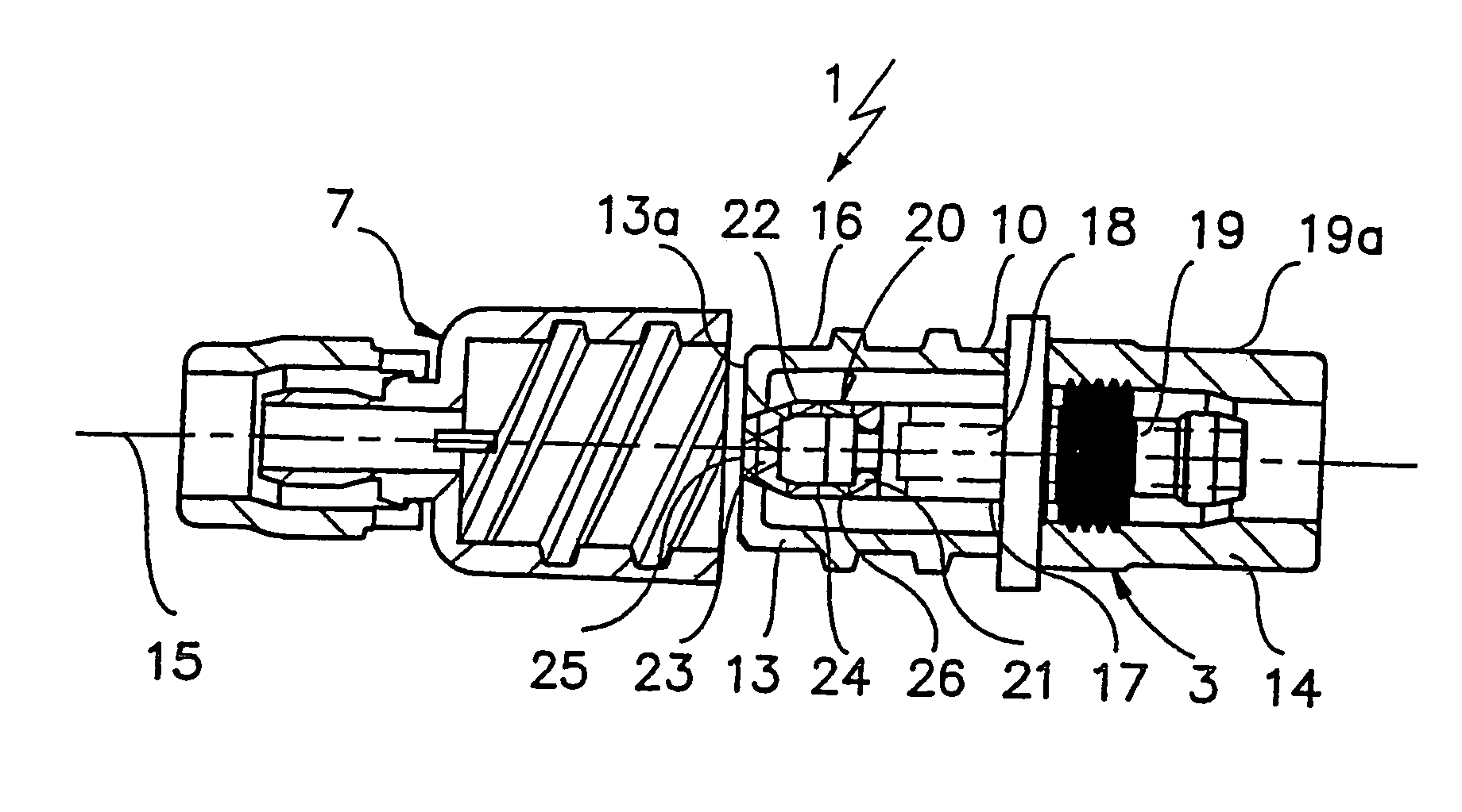
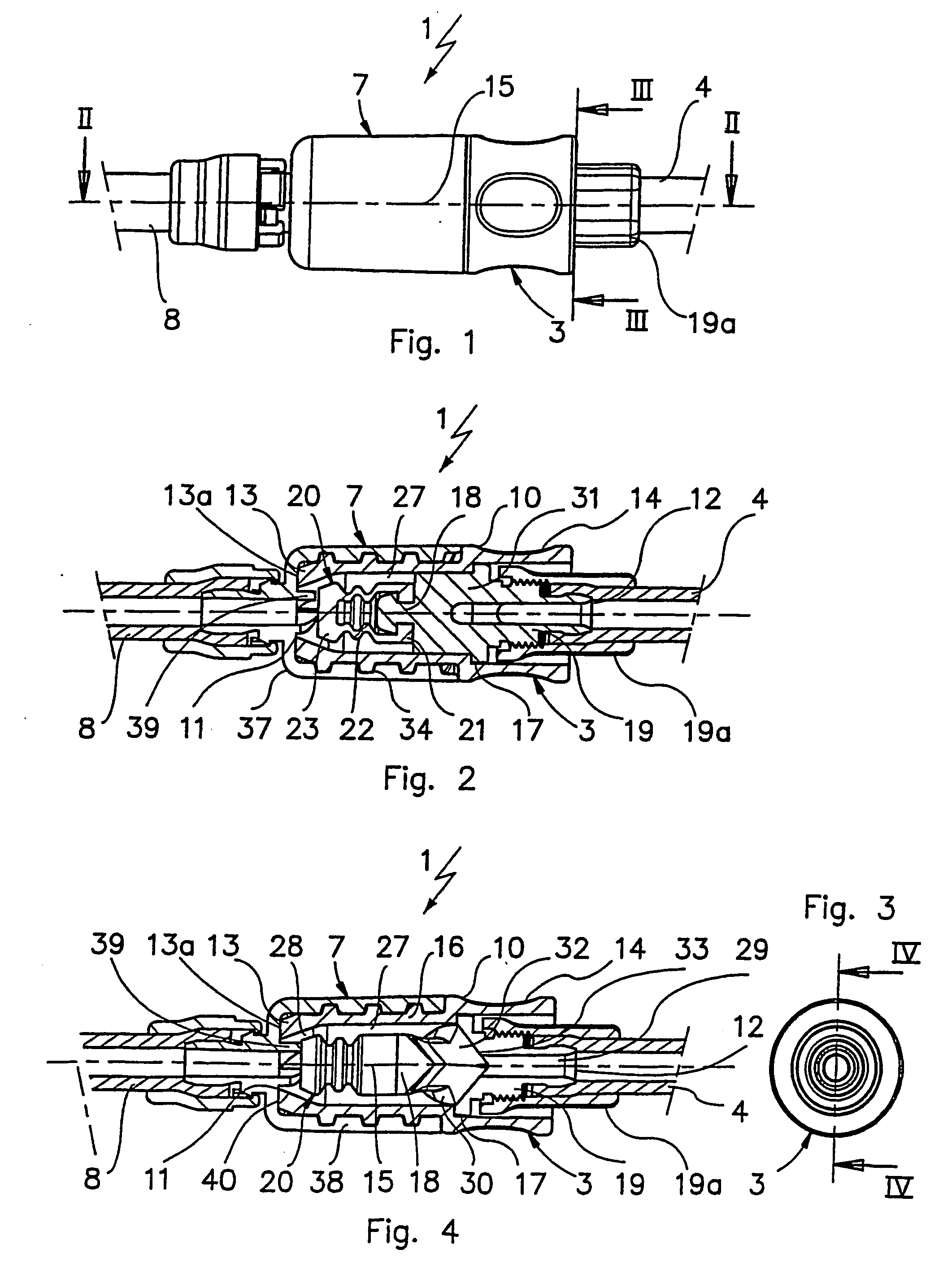
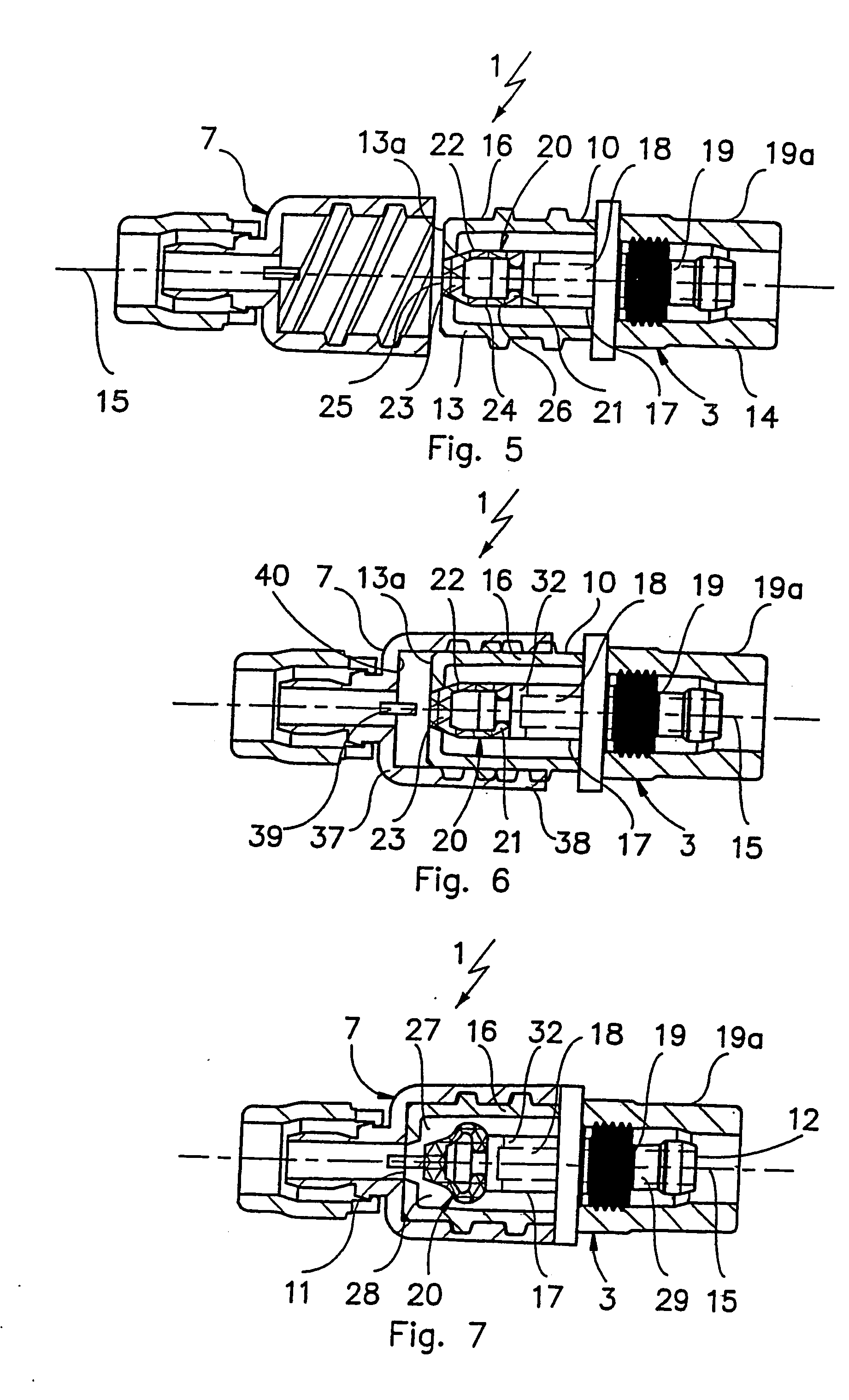
[0042] With reference to the attached figures, reference number 1 is a general reference for a connecting device for tubes for medical use in accordance with the present invention.

[0043] In particular, FIG. 9 shows an application of the device 1 to a line for peritoneal dialysis, bearing the general reference number 2. In greater detail, the device 1 comprises a connection element 3 attached to the end of a tube 4, the latter being designed to be placed in fluid communication with the peritoneal cavity 5 of a patient 6. The device 1 also includes an auxiliary connection element 7 attached to the end of another tube 8 connected to two or more containers 9 that may be used for infusing fresh fluid into the peritoneal cavity or evacuating fluid from the same peritoneal cavity. The two connector elements 3 and 7 are designed to be connected mechanically together, when in use, to allow fluid communication between the pipes 4 and 8 described above, allowing infusion or, alternatively, ev...


PUM


Abstract

A description is given of a connecting device for tubes for medical use having a connection element (7) comprising a main body designed to be attachable to the end of a first tube, and a shut-off element made of an elastically deformable material and at least partly housed inside the main body, to allow or prevent, as required, fluid communication through the main body. The shut-off element has a longitudinal axis of symmetry and is designed to deform symmetrically. Also described are a tube and a peritoneal dialysis line using the connection element described above.

Description

BACKGROUND OF THE INVENTION [0001] The present invention relates to a connection element and a connecting device for tubes for medical use. [0002] As is well known, in the medical field it is often necessary to set up fluid communication between pipes designed to carry liquids. [0003] At the present time, to create a mechanical connection between consecutive terminal portions of two tubes, use may be made of connector elements attachable to the mutually opposing ends of the two tubes to be connected. Each connector element comprises a first portion that attaches onto the terminal portion of the respective tube, and a second portion designed for removable engagement on the other connector element. The mechanical connection between the two connectors is typically provided by threaded or bayonet couplings, Luer connections and the like. [0004] It is however clear that connector devices described above can only provide a mechanical connection between the two terminal portions of tube an...

Claims


Application Information

Patent Timeline
IPC IPC(8): A61M39/04A61M39/10A61M39/26
CPCA61M39/045A61M2039/1033A61M39/26A61M39/10
Inventor PARRINO, ANDREACOLLI, GUIDO
Owner GAMBRO LUNDIA AB
Why Eureka
Try Eureka