Apparatus and method for a low jitter predriver for differential output drivers

a low jitter, differential output technology, applied in logic circuit coupling/interface arrangement, pulse technique, baseband system details, etc., can solve the problems of undesirable common mode variation, common mode voltage fluctuation of output differential signals,

Inactive Publication Date: 2005-09-29
INTEL CORP
View PDF9 Cites 9 Cited by
  • Summary
  • Abstract
  • Description
  • Claims
  • Application Information

AI Technical Summary

Problems solved by technology

Common mode voltage fluctuation of the output differential signals also presents a problem since receiver circuitry requires a stable, common mode input voltage for optimal performance

Method used


Image

  • Apparatus and method for a low jitter predriver for differential output drivers
  • Apparatus and method for a low jitter predriver for differential output drivers
  • Apparatus and method for a low jitter predriver for differential output drivers

Examples


Embodiment Construction

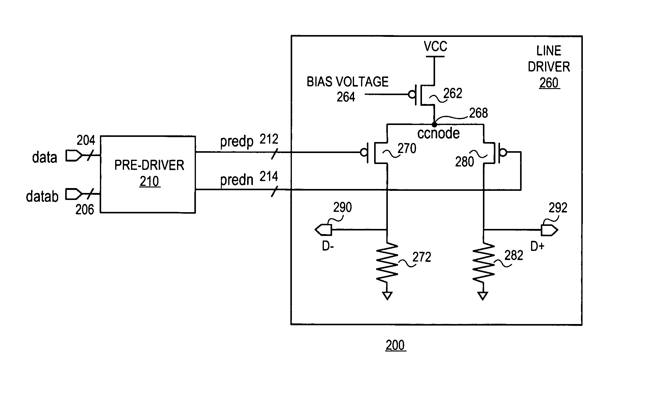
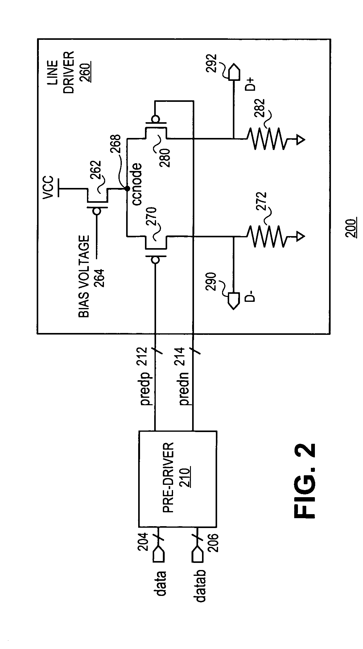
[0013] A method and apparatus for a low jitter predriver for differential output drivers are described. In one embodiment, the predriver comprises a first pair of cross-coupled devices to receive a data input signal. In addition, a second pair of cross-coupled devices receive a complement data input signal. The first and second cross-coupled devices are used to charge an output node and a complement output node in opposite directions to generate a differential predriver signal pair. In one embodiment, the circuit differential predriver signals pair to open / close a pair of output driver switches to generate a differential output driver signal pair. In one embodiment, the first and second pair of cross-couple devices comprise N-channel metal oxide semiconductor (NMOS) devices.

[0014] In the following description, numerous specific details such as logic implementations, sizes and names of signals and buses, types and interrelationships of system components, and logic partitioning / integ...


PUM


Abstract

A method and apparatus for a low jitter predriver for differential output drivers. In one embodiment, the predriver comprises a pull-up circuit having at least one pull-up device of a first device type and a pull-down circuit having at least one pull-down device of the first device type In one embodiment, the pull-up circuit and the pull-down circuit to charge an output node and a complement output node in opposite directions to generate a differential predriver signal pair. Accordingly, using the pull-up and pull-down circuits, the predriver circuit generates differential output signals. In one embodiment, the pull-up device and the pull-down device comprise N-channel metal oxide semiconductor (NMOS) devices. Other embodiments are described and claimed.

Description

FIELD OF THE INVENTION [0001] One or more embodiments of the invention relate generally to the field of integrated circuit and computer system design. More particularly, one or more of the embodiments of the invention relates to a method and apparatus for a low jitter predriver for differential output drivers. BACKGROUND OF THE INVENTION [0002] High speed serial differential interfaces depend on extremely low output jitter to maintain error-free (or low bit-error rate) communication. Common mode voltage fluctuation of the output differential signals also presents a problem since receiver circuitry requires a stable, common mode input voltage for optimal performance. Conventionally, current mode differential output drivers are limited in architecture, generally consisting of a simple current source and switches which channel current to either a data input line or a complementary data input line. [0003] Differential output drivers generally work in conjunction with predriver circuitry...

Claims


Application Information

Patent Timeline
IPC IPC(8): H03K19/003H03K19/0185H03K19/094H04L25/02
CPCH03K19/00323H04L25/028H04L25/0272H03K19/018528
Inventor LEVIN, ALEXANDER
Owner INTEL CORP
Why Eureka
Try Eureka