
Filter circuit

Active Publication Date: 2005-09-29
AVAGO TECH INT SALES PTE LTD +1
View PDF11 Cites 15 Cited by
  • Summary
  • Abstract
  • Description
  • Claims
  • Application Information

AI Technical Summary

Benefits of technology

[0030] It is an advantage of the present invention that a process used for producing the baluns also opens up the possibility to generate monolithic coils (spiral-shaped inductivities) with high Q factors, which can then be used as elements of the balun or additionally as adaption elements. At present, these adaption elements in conventional filter circuits are realized as external elements outside the filter chips, which causes the above-mentioned problems.
[0031] It is another advantage of the present invention that additionally to the inductivities capacitors can be produced in a simple way, which means also as monolithic elements on the filter chip since different layers of dielectric materials are used for producing the BAW resonators. The capacitors generated that way can be used as adaption capacitors or as coupling capacitors.
[0032] Compared to conventional BAW production methods, merely minor modifications are required, which are required to produce the thick metals which are required to obtain the elements (balun, inductivity, capacitor). Additional masking layers will be required, which, however, lead only to minor increase of the overhead of the process.

Problems solved by technology

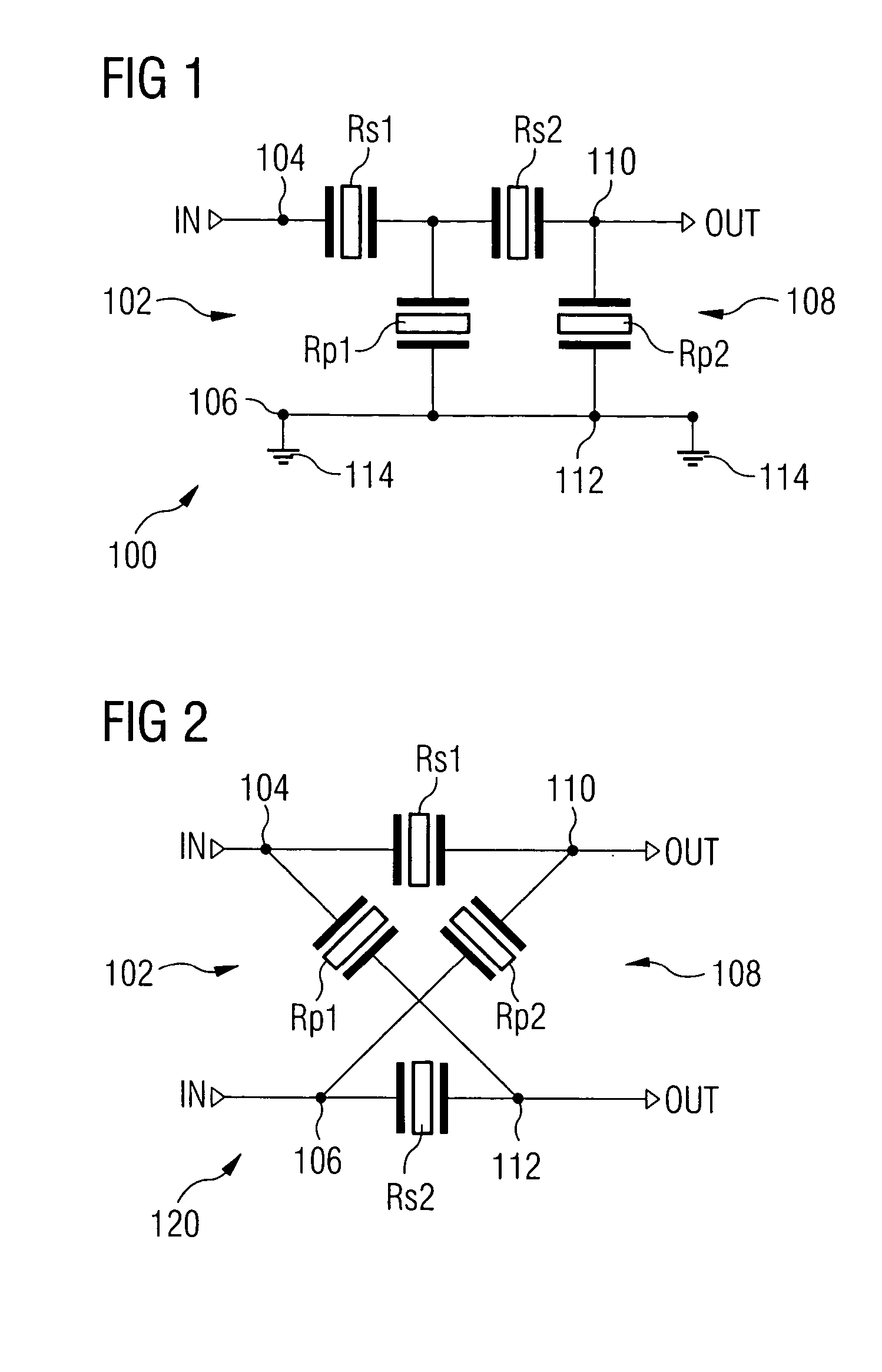
However, in the ladder filter 100, there is merely the possibility to receive an unbalanced input signal and to output a respective unbalanced output signal.
There are, however, applications where it is required to perform a transformation / conversion of an unbalanced input signal into a balanced output signal, or a transformation / conversion of a balanced input signal into an unbalanced output signal.
The usage of discrete baluns before or after the filters is a possibility but increases the number of required components and the required space on the printed circuit board.
In surface acoustic wave filters (SAW filters), an acoustic balancing function can be implemented without additional components, it does, however, decrease the behavior of the overall filter significantly.
Further, this balancing function leads to the filter being very sensitive against electrostatic discharges and further the possibilities of manipulating powers are limited drastically, i.e. the transmittable powers across such a filter structure are very low.
It is another disadvantage of the coupled SAW filter that the response of these filters is generally worse than the response of impedance element filters, particularly the so-called roll-off or the selectivity near the pass band.
However, this solution has significant disadvantages for the practical application of such a filter and is particularly disadvantageous in that it can only be related to floating differential loads, which means no RF leaking current against ground is allowed.
In connection with BAW filters, no solution is known that would suggest in what way an impedance transformation could be performed.

Method used


Image

  • Filter circuit
  • Filter circuit
  • Filter circuit

Examples


first embodiment

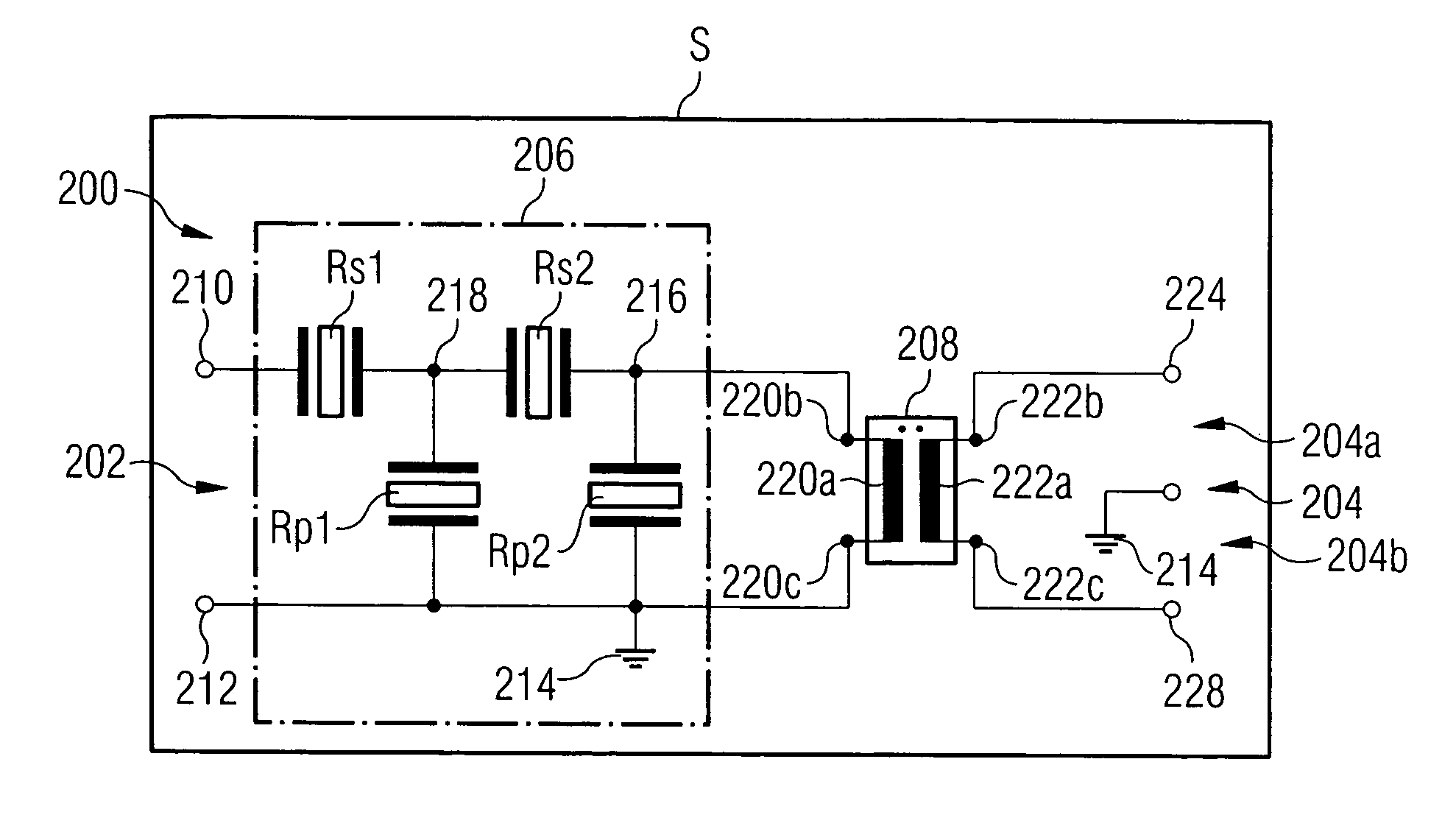
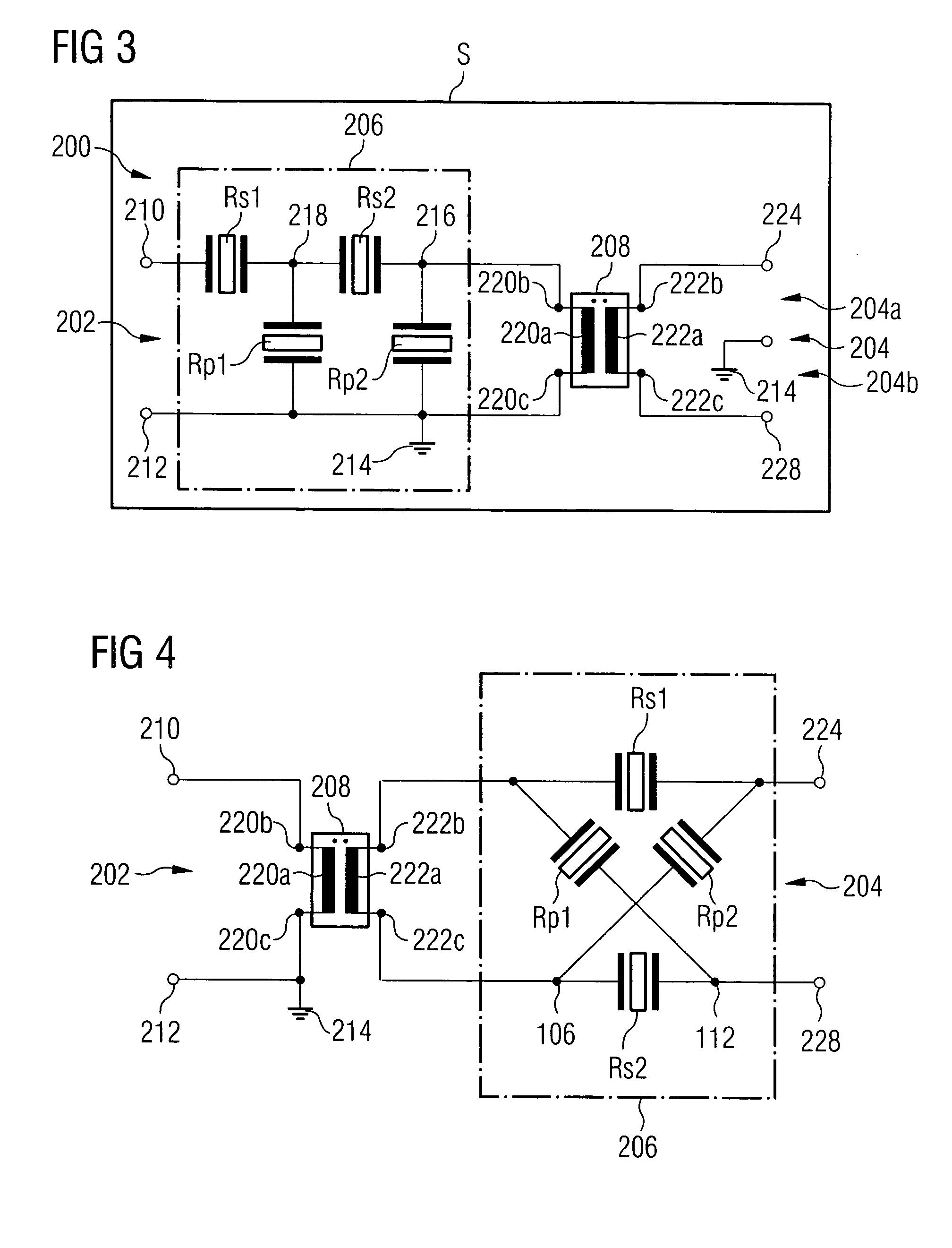
[0042]FIG. 3 shows the inventive filter circuit 200. The filter circuit 200 comprises an unbalanced terminal 202 and a balanced terminal 204 with the two balanced ports 204a and 204b. A series circuit consisting of a filter stage 206 and a balun 208 is connected between the unbalanced terminal 202 and the balanced terminal 204. In the embodiment illustrated in FIG. 3, the filter stage 206 is an unbalanced filter stage in the form of a ladder filter as it has been described exemplarily with regard to FIG. 1. The filter stage 206 comprises two series resonators Rs1 and Rs2 as well as two parallel resonators Rp1 and Rp2.

[0043] The unbalanced terminal 202 comprises a first node 210 and a second node 212. The second node 212 is connected to a reference potential 214, e.g. ground. The filter stage 206 comprises a series circuit consisting of the two series resonators Rs1 and Rs2 connected between the first node 210 and a third node 216. The first parallel resonator Rp1 is connected betwee...

second embodiment

[0054] Further embodiments of the present invention will be discussed below in more detail with reference to FIGS. 4-6, wherein FIG. 4 shows a second embodiment where a lattice filter structure is used instead of the ladder filter structure used in FIG. 3, connected to the balanced input 204 of the filter circuit. The balun 208 is connected between the filter stage 206 and the unbalanced input 202.

[0055] In the embodiment illustrated in FIG. 4, in the filter stage 206, a first series resonator Rs1 is connected between the first terminal 222b of the second coil 222a of the balun 208 and the terminal 224 of the balanced output 204. A second series resonator Rs2 is connected between the second terminal 222c of the second coil 222a of the balun 208 and the second terminal 228 of the balanced output 204. A first parallel resonator Rp1 is connected between the first terminal 222b of the second coil 222a and the second node 228 of the balanced terminal 204, and a second parallel resonator ...


PUM


Abstract

A filter circuit comprises a balanced port, an unbalanced port and a substrate. A series circuit of a filter stage and a balun is disposed between the balanced port and the unbalanced port. The balun and the filter stage are formed on the substrate.

Description

CROSS-REFERENCE TO RELATED APPLICATION [0001] This application is a continuation of copending International Application No. PCT / EP03 / 07015, filed Jul. 1, 2003, which designated the United States and was not published in English.BACKGROUND OF THE INVENTION [0002] 1. Field of the Invention [0003] The present invention relates to a filter circuit, particularly to a filter circuit for converting unbalanced / balanced signals into balanced / unbalanced signals, and here particularly to a filter circuit comprising BAW resonators (BAW=bulk acoustic wafer). Further, the present invention relates to a filter circuit with a plurality of BAW resonators, which enables a transformation of impedance levels between an input port and an output port of the filter circuit. [0004] 2. Description of the Related Art [0005] RF filters based on resonators, such as BAW filters, have two basic topologies, which will be discussed in more detail with regard to FIGS. 1 and 2. [0006] The first topology (see FIG. 1)...

Claims


Application Information

Patent Timeline
IPC IPC(8): H01F17/00H03H7/42H03H7/38H03H9/00H03H9/58H03H9/70
CPCH01F17/0006H03H9/0095H03H7/42H01F2021/125H03H9/58
Inventor AIGNER, ROBERTELLAE, JUHA SAKARIMARKSTEINER, STEPHANTIMME, HANS-JORG
Owner AVAGO TECH INT SALES PTE LTD
Learn More