A Surface Plasmon Resonance Sensor Based on Black Phosphorus-Planar Waveguide

A surface plasmon and resonant sensor technology, applied to instruments, scientific instruments, measuring devices, etc., can solve the problems of low Q factor and sensitivity, high energy loss of SPR sensors, etc., to achieve improved imaging sensitivity, fast detection speed, and imaging The effect of high sensitivity

Active Publication Date: 2022-03-29
CENTRAL SOUTH UNIVERSITY OF FORESTRY AND TECHNOLOGY
View PDF3 Cites 0 Cited by
  • Summary
  • Abstract
  • Description
  • Claims
  • Application Information

AI Technical Summary

Problems solved by technology

[0003] Traditional SPR sensors have disadvantages such as high energy loss, low Q factor and low sensitivity (S. Hayashi, D.V. Nesterenko, and Z. Sekkat, Appl. Phys. Express 8, 022201 (2015)), (G.Zheng, X. Zou, Y. Chen, L. Xu, and W. Rao, Opt Mater 66,171 (2017)), (S.Hayashi, D. V. Nesterenko, A. Rahmouni, and Z. SekkatAppl. Phys. Lett. 108,051101 ( 2016))

Method used


Image

  • A Surface Plasmon Resonance Sensor Based on Black Phosphorus-Planar Waveguide
  • A Surface Plasmon Resonance Sensor Based on Black Phosphorus-Planar Waveguide
  • A Surface Plasmon Resonance Sensor Based on Black Phosphorus-Planar Waveguide

Examples


Embodiment 1

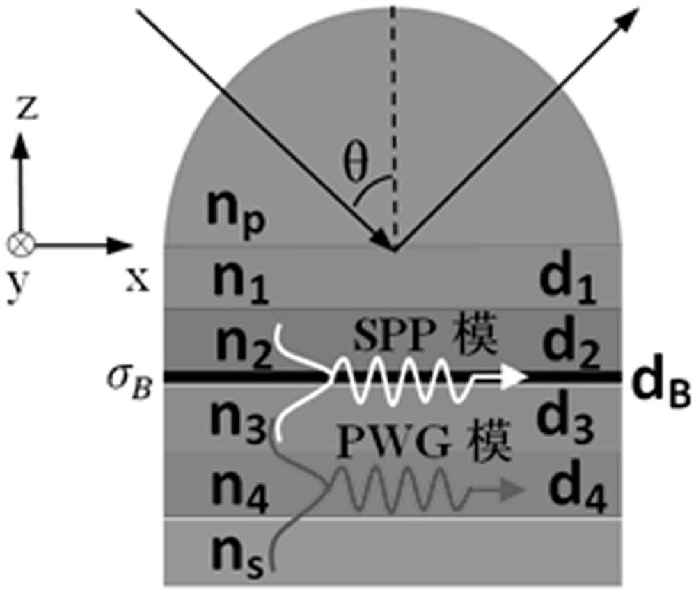
[0022] like figure 1 As shown, a SPR resonance sensor based on BP / planar waveguide, from top to bottom are germanium prism, CaF 2 , quartz crystal, BP, CaF 2 , quartz crystal layer and sensing layer, the thicknesses of the second to sixth layers are respectively set to 10.1, 8.4, 2.62×10 -3 , 28, 9.2 μm. . CaF 2 , lower CaF 2 1. The quartz crystal and the sensing layer constitute a planar dielectric waveguide (referred to as PWG). In order to illustrate the performance of this structure, the advantages of the present invention will be further described in conjunction with specific examples below.

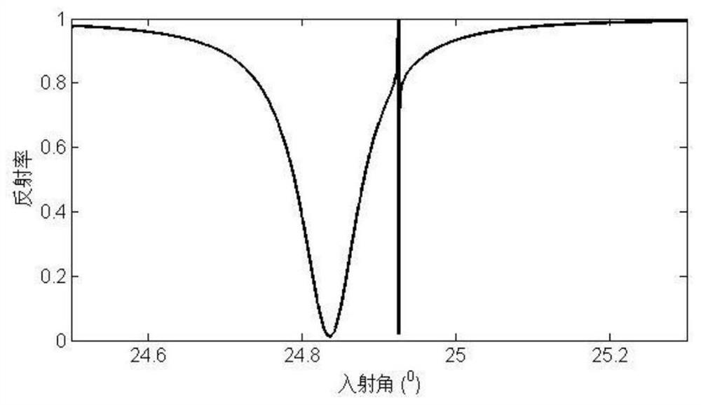
[0023] A beam of TM polarized light with a wavelength of 30 μm enters the prism, the sawtooth direction of BP is located in the incident plane, and the light passes through the CaF 2 , quartz crystal and BP, enter the next layer of CaF 2 , the SPP mode is generated at the upper and lower interface of BP, and its effective refractive index is 1.679. In order to generate a str...

Embodiment 2

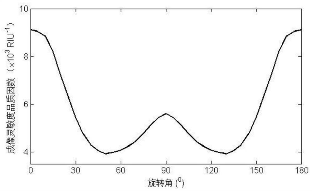
[0025] Embodiment 2: When the sensor rotates around the z-axis in the xoy plane, since the in-plane conductivity of BP is anisotropic, the sensitivity quality factor will change with the rotation angle. image 3 is the relationship between the sensitivity figure of merit of the device of the present invention and the rotation angle. The sensitivity extremum takes on a "W" shape as the rotation angle changes (the rotation angle is the angle between the BP sawtooth direction and the incident plane). When the rotation angle is 0, the quality factor of the imaging sensitivity of the sensor is the highest (9.12×10³ RIU -1 ), when the rotation angle increases to 50 0 When , the figure of merit reaches the lowest value (3.92×10³ RIU -1 ). As the rotation angle continues to increase, the quality factor increases, and at a rotation angle of 90 0 When , the quality factor of imaging sensitivity reaches the second extreme value (5.60×10 3 RIU -1 ). Due to the rotational symmetry o...


PUM

PropertyMeasurementUnit
thicknessaaaaaaaaaa
thicknessaaaaaaaaaa
thicknessaaaaaaaaaa

Abstract

A surface plasmon resonance sensor based on black phosphorus-planar waveguide, from top to bottom, includes a transparent germanium prism, an upper calcium fluoride layer, an upper quartz crystal, a black phosphorus layer, a lower calcium fluoride layer, a lower quartz crystal and The sensing layer; the lower calcium fluoride layer, the lower quartz crystal and the sensing layer constitute a planar dielectric waveguide; the TM polarized light enters the prism, passes through the upper calcium fluoride layer, the upper quartz crystal and the black phosphorus layer, and then enters the lower calcium fluoride layer, under the wave vector matching condition, the incident light is converted into the surface plasmon mode at the upper and lower interfaces of the black phosphorus layer, thereby generating SPR resonance; the effective refraction of the surface plasmon mode and the planar dielectric waveguide film The rate is the same or close, and electromagnetic coupling occurs, forming a Fano resonance trough in the reflection curve. Compared with the traditional SPR sensor, the invention can improve the imaging sensitivity by introducing the black phosphorus and the planar waveguide.

Description

technical field [0001] The invention relates to a resonance sensor, in particular to a surface plasmon resonance sensor based on black phosphorus-planar waveguide. Background technique [0002] Surface plasmon resonance (SPR) is a collective oscillation formed by the coupling of free electrons bound at the metal-dielectric interface and electromagnetic waves. The change of the refractive index of liquid or gas can be monitored in real time by using SPR-based biosensing technology. SPR sensing analysis has the advantages of more accurate detection capability, non-labeled analysis, stability and reliability, and small sample demand, and can be used for the analysis and detection of toxic gases, chemical biomolecules, and living cells. [0003] Traditional SPR sensors have disadvantages such as high energy loss, low Q factor and low sensitivity (S. Hayashi, D.V. Nesterenko, and Z. Sekkat, Appl. Phys. Express 8, 022201 (2015)), (G.Zheng, X. Zou, Y. Chen, L. Xu, and W. Rao, Opt...

Claims


Application Information

Patent Timeline
Patent Type & Authority Patents(China)
IPC IPC(8): G01N21/552
CPCG01N21/553
Inventor 贺梦冬鲁登云李卫周虎张新民李建波王凯军
Owner CENTRAL SOUTH UNIVERSITY OF FORESTRY AND TECHNOLOGY
Why Eureka
Try Eureka