Image forming apparatus and method

a technology of image forming and forming dots, which is applied in the direction of inking apparatus, printing apparatus, other printing apparatus, etc., can solve the problems of slow recording speed, inability to control smearing after transfer, and long time-consuming smearing of recording dots, so as to achieve high-quality image formation, suppress landing interference, and smearing and spreading of ink

Inactive Publication Date: 2005-09-29
FUJIFILM CORP
View PDF3 Cites 14 Cited by
  • Summary
  • Abstract
  • Description
  • Claims
  • Application Information

AI Technical Summary

Benefits of technology

[0009] The present invention has been contrived in view of such circumstances, and an object thereof is to provide an image forming apparatus and method which can achieve high-quality image formation by controlling the viscosity of deposited ink in order to reduce interference between liquid droplets on the recording medium and movement of the liquid (landing interference), and hence cause the droplets to become fixed reliably in a satisfactory dot configuration.

Problems solved by technology

However, in the recording apparatus described in Japanese Patent Application Publication No. 5-4342, time is required for the recording droplets to dry on the intermediate transfer medium, and this leads to a decline in recording speed.
Furthermore, if the image is transferred in a state where an electric field is applied, as in Japanese Patent Application Publication No. 5-4342, then it is not possible to control smearing after transfer.
On the other hand, in the recording apparatus described in Japanese Patent Application Publication No. 5-4343, even if it is possible to restrict the rate of smearing of the recording dots by applying an electric field, smearing of the recording dots still continues for a long period of time after the electric field is removed.

Method used


Image

  • Image forming apparatus and method
  • Image forming apparatus and method
  • Image forming apparatus and method

Examples


first embodiment

; General Configuration of an Inkjet Recording Apparatus

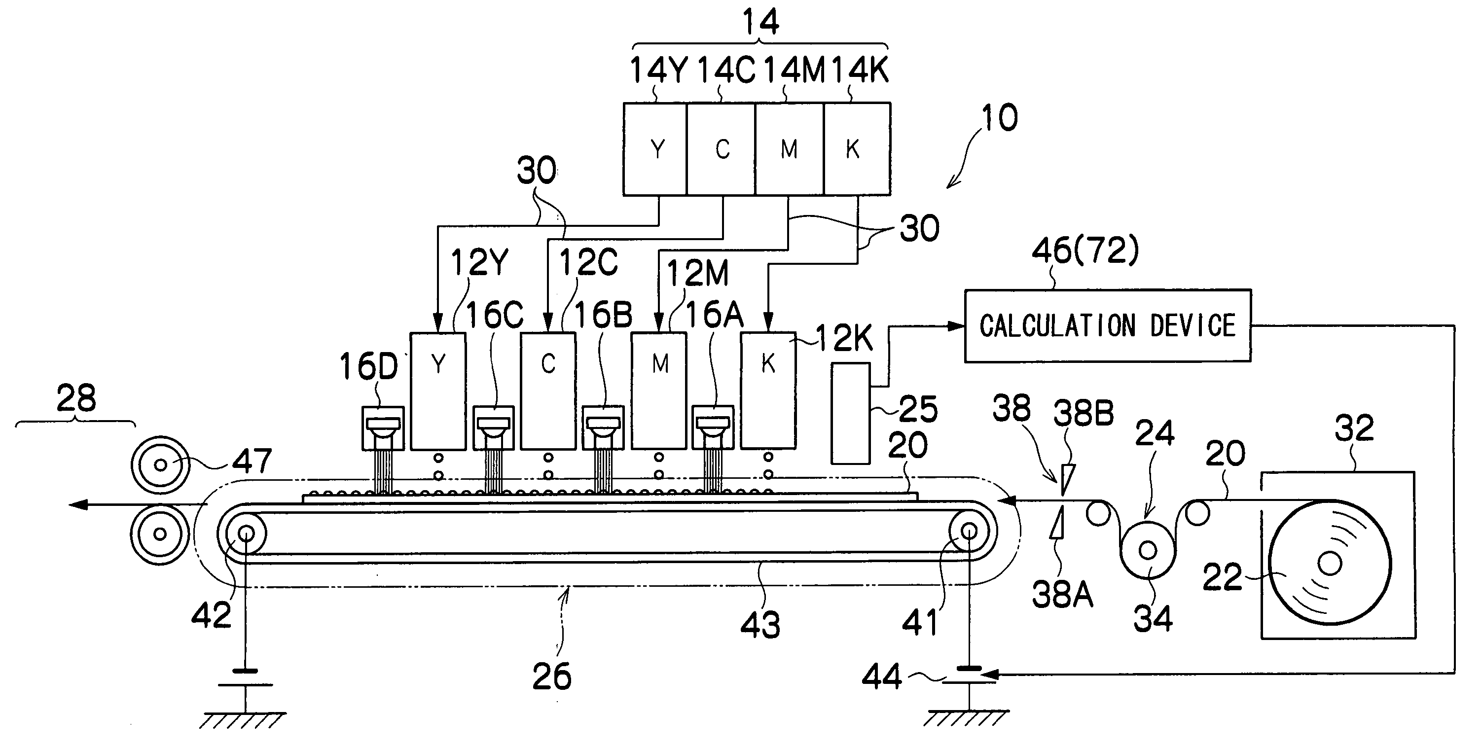
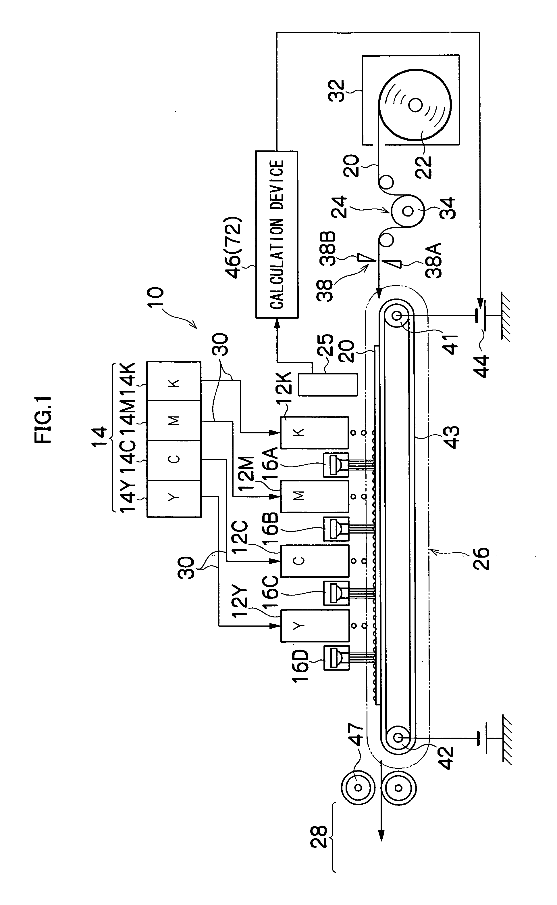
[0048]FIG. 1 is a general schematic drawing of an inkjet recording apparatus for forming an image by ejecting inks as droplet onto a recording medium, according to an embodiment of the present invention.

[0049] As shown in FIG. 1, the inkjet recording apparatus 10 comprises: a plurality of print heads 12K, 12M, 12C, and 12Y for ink colors of black (K), magenta (M), cyan (C), and yellow (Y), respectively; an ink storing / loading unit 14 for storing inks (in this embodiment, ultraviolet (UV) curable inks which have electrorheological properties) to be supplied to the print heads 12K, 12M, 12C, and 12Y; a medium supply unit 22 for supplying a medium (recording medium) 20; a decurling unit 24 for removing curl in the medium 20; a surface potential sensor 25 for measuring potential on surface of the medium 20, an electrostatic suction belt conveyance unit 22 disposed facing the nozzle face (ink-droplet ejection face) of the print uni...

second embodiment

[0121]FIG. 8 is a schematic drawing showing the principal components of an image forming apparatus relating to a second embodiment of the present invention. In FIG. 8, members which are the same as or similar to those in FIG. 1 are labeled with the same reference numerals and description thereof is omitted here. In addition to the composition shown in FIG. 1, desirably, a composition is added in which earthed electrode plates 94 are respectively disposed immediately below the nozzle surfaces of the heads 12K, 12M, 12C and 12Y, and the frames of the heads 12K, 12M, 12C and 12Y are also earthed, as shown in FIG. 8. Of course, holes 95 are formed in the electrode plates 94 in order that the liquid ejected from the nozzles 51 can pass through same, but apart from the area of these holes 95, the ejection surfaces of the head 50 are covered and hence the electrode plates 94 function as electromagnetic shielding members.

[0122] By means of this composition, the flow of the lines of electri...

third embodiment

[0123]FIG. 9 is a schematic drawing showing the principal components of an image forming apparatus relating to a third embodiment of the present invention. In FIG. 9, members which are the same as or similar to those in FIG. 1 are labeled with the same reference numerals and description thereof is omitted here. In FIG. 1, UV light sources 16A to 16D are provided respectively downstream of the heads 12K, 12M, 12C and 12Y and UV light is irradiated separately for each ink color. However, instead of this composition, it is also possible to adopt a configuration in which a UV light source 16D is only provided downstream of the last color head (in this case, the yellow head 12Y) as shown in FIG. 9, and UV light is irradiated only once by this UV light source 16D.

[0124] Since an electric field continues to be applied to the ink droplets deposited on the medium 20, during the holding and conveyance of the medium 20 on the electrostatic suction belt 43, it is possible to prevent smearing b...


PUM


Abstract

The image forming apparatus comprises: an ejection head which ejects ink having electrorheological properties toward a recording medium; an electric field application device which applies an electric field to droplets of the ink deposited on a surface of the recording medium; an electric field intensity control device which controls intensity of the electric field in such a manner that the ink in the droplets has a prescribed viscosity; and a fixing promotion device which carries out processing for promoting fixing of the ink on the recording medium, in a state where the electric field is applied by the electric field application device.

Description

BACKGROUND OF THE INVENTION [0001] 1. Field of the Invention [0002] The present invention relates to an image forming apparatus and method, and more particularly, to an image forming technology suitable for an image forming apparatus, such as an inkjet recording apparatus which forms images on a recording medium by ejecting liquid droplets from nozzles. [0003] 2. Description of the Related Art [0004] Japanese Patent Application Publication Nos. 5-4342 and 5-4343 disclose technology for using an electrorheological fluid in a recording apparatus based on an inkjet type of recording head, in order to prevent smearing and color mixing of ink, and the like, on the recording medium. [0005] Japanese Patent Application Publication No. 5-4342 discloses a recording apparatus in which a recording liquid having electrorheological properties is formed into droplets by a recording head and caused to adhere to an intermediate transfer medium having an electric field created on the surface thereof,...

Claims


Application Information

Patent Timeline
Patent Type & Authority Applications(United States)
IPC IPC(8): B41J2/085B41J2/01B41J11/00
CPCB41J11/002B41J2202/20B41J2002/14459B41J11/009B41J11/0021
Inventor KADOMATSU, TETSUZOKONNO, MASAAKI
Owner FUJIFILM CORP
Why Eureka
Try Eureka