Cascaded difference frequency generator using resonant structure

a frequency generator and cascade technology, applied in the direction of instruments, light demodulation, optical light guides, etc., can solve the problems of degrading conversion efficiency, and achieve the effect of improving conversion efficiency

Inactive Publication Date: 2005-09-29
ELECTRONICS & TELECOMM RES INST
View PDF6 Cites 12 Cited by
  • Summary
  • Abstract
  • Description
  • Claims
  • Application Information

AI Technical Summary

Benefits of technology

The present invention is about a new way to make a resonant cascaded difference frequency generator that can improve the efficiency of converting light to different frequencies using second-order nonlinear optical phenomena. The new resonant structure helps to enhance the conversion process.

Problems solved by technology

The technical problem addressed in this patent text is to improve the conversion efficiency in the optical phenomenon related to second-order nonlinearity, by searching materials with higher nonlinear structures, composing new materials, finding new methods of phase-matching, and fabricating a nonlinear material into an optical waveguide form to increase the interaction of three light waves to be mixed. Additionally, the text discusses the difference frequency generation process and its advantages and disadvantages for wavelength conversion in ultra-high speed optical communication.

Method used


Image

  • Cascaded difference frequency generator using resonant structure
  • Cascaded difference frequency generator using resonant structure
  • Cascaded difference frequency generator using resonant structure

Examples


Embodiment Construction

[0016] Hereinafter, resonant cascaded difference frequency generators according to embodiments of the present invention will be explained with reference to the appended drawings. However, those skilled in the art will appreciate that various adaptations and modifications of the following preferred embodiments can be made without departing from the scope and spirit of the invention. Therefore, it will be understood that the scope of invention does not limited to the following described embodiments.

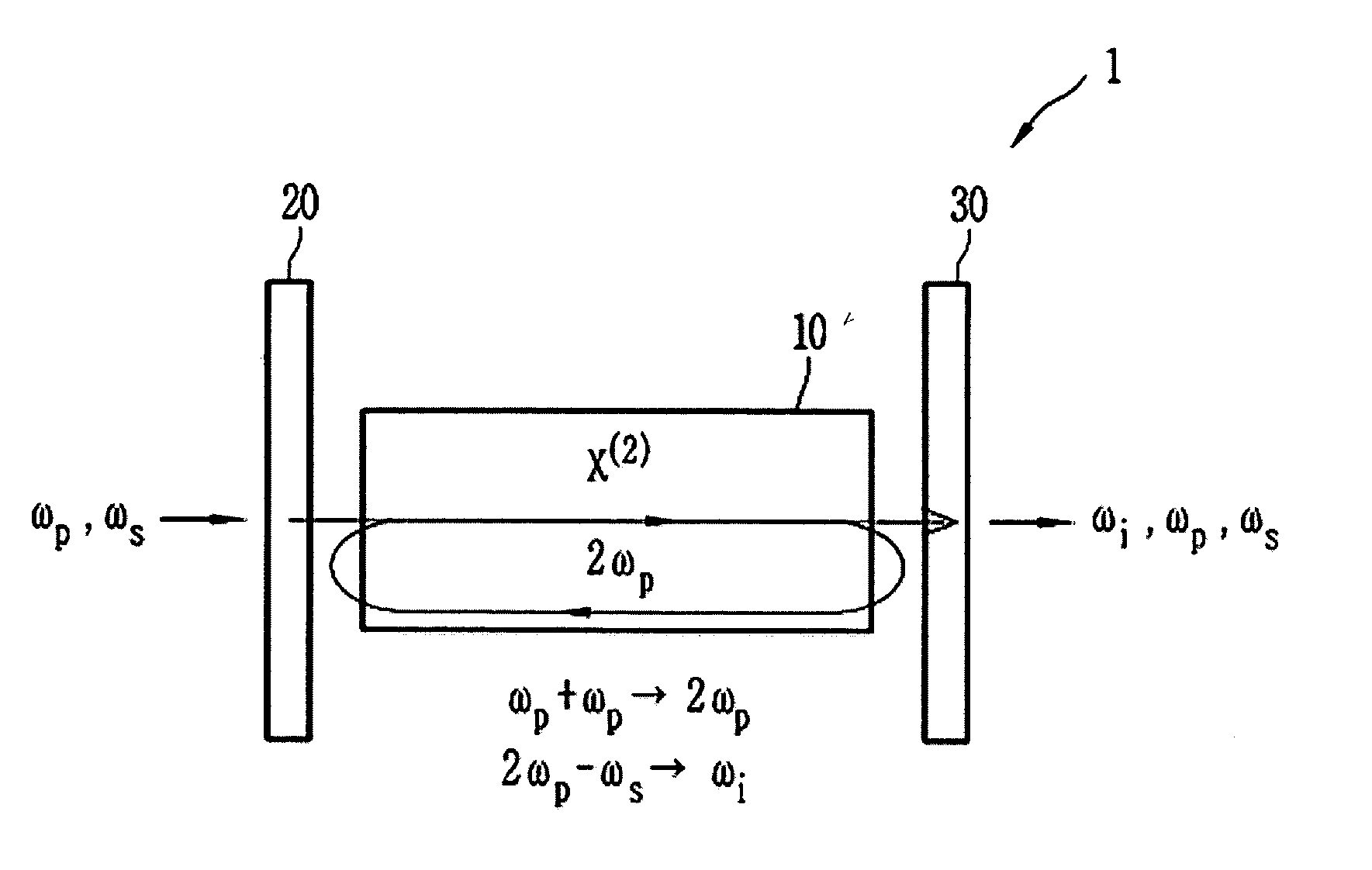
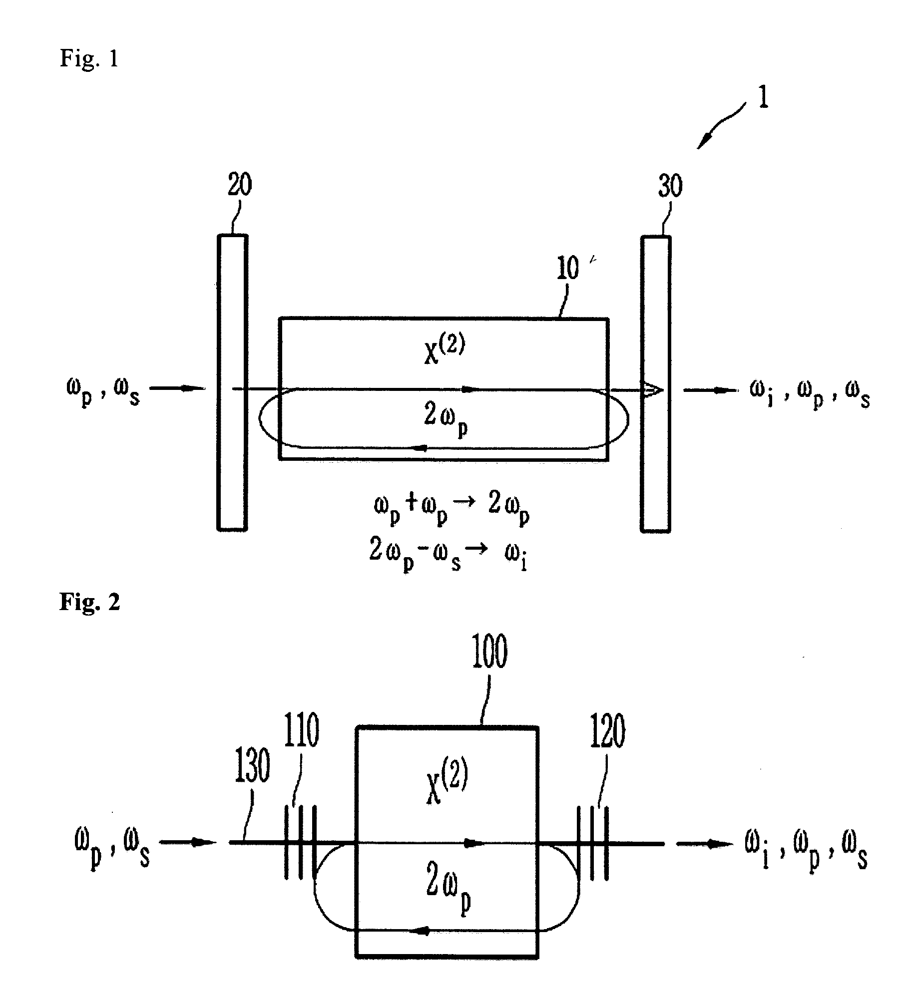
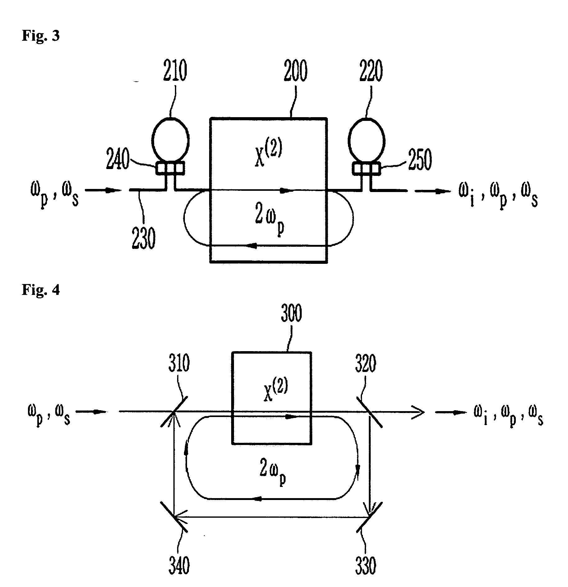
[0017]FIG. 1 is a schematic diagram of a resonant cascaded difference frequency generator according to one embodiment of the present invention.

[0018] The resonant cascaded difference frequency generator 1 includes resonant structures 20 and 30 receiving a pump light (Wp) and a signal light (Ws) to resonate the second harmonic wave (2Wp) of the pump light (Wp), and a nonlinear medium 10 placed inside the resonant structures to generate the second harmonic wave (2Wp) and then generate a con...


PUM


Abstract

Provided is a resonant cascaded difference frequency generator that is capable of improving the conversion efficiency of the second-order nonlinear optical phenomena by resonating the second harmonic wave of a pump light. The resonant cascaded difference frequency generator includes: a nonlinear medium, which receives a pump light and a signal light and then generates the second harmonic wave of the pump light through second harmonic generation, in a cascaded way generates a converted light of a difference frequency through difference frequency generation between the signal light and the second harmonic wave; and a resonant structure that resonates the second harmonic wave of the pump light on the basis of the nonlinear medium.

Description


Claims


Application Information

Patent Timeline
Owner ELECTRONICS & TELECOMM RES INST
Why Eureka
Try Eureka