Surface acoustic wave sensor and radio frequency identification interrogator fixture

a surface acoustic wave and radio frequency identification technology, applied in the field of sensing methods and systems, can solve the problems of faulty readings, tire pressure but not robust, and generally relatively complex devices and expensive or alternatively not particularly robus

Inactive Publication Date: 2005-09-29
HONEYWELL INT INC
View PDF18 Cites 7 Cited by
  • Summary
  • Abstract
  • Description
  • Claims
  • Application Information

AI Technical Summary

Benefits of technology

[0018] The patch itself can be formed from a rubber material. The antenna block preferably is configured from a material that is not affected by RF signals. Similarly, the antenna cover preferably comprises a material that is not affected by RF signals. The top locator block can be formed from an amorphous thermoplastic polyetherimide material. Such a system can be implemented as a combined SAW and RFID interrogator standards fixture which can send a frequency signal to the patch (i.e., SAW patch) at a fixed distance and orientation in order to verify that the SAW and RFID sensor (i.e., the SAW patch) is functioning properly and can send a signal pack to the test fixture.

Problems solved by technology

Such devices are generally relatively complex and expensive or alternatively are not particularly robust.
This system provides an indication of low tire pressure but is not robust.
For example mud or other debris on the wheels may cause faulty readings.
Clearly such a system simply cannot provide a reading of actual tire pressure.
However, if the tire in a rut or is parked on uneven ground, a faulty low-pressure reading is likely to be generated.
More complicated systems are capable of monitoring tire pressure.
Conventional wireless systems, however, are not durable and are expensive to design and produce.
The housing and base of the sensor must also not be placed into a condition in which an electrical short runs from the housing to the base, causing a frequency shift or error in the sensor measurements.

Method used


Image

  • Surface acoustic wave sensor and radio frequency identification interrogator fixture
  • Surface acoustic wave sensor and radio frequency identification interrogator fixture
  • Surface acoustic wave sensor and radio frequency identification interrogator fixture

Examples


Embodiment Construction

[0031] The particular values and configurations discussed in these non-limiting examples can be varied and are cited merely to illustrate at least one embodiment of the present invention and are not intended to limit the scope of the invention.

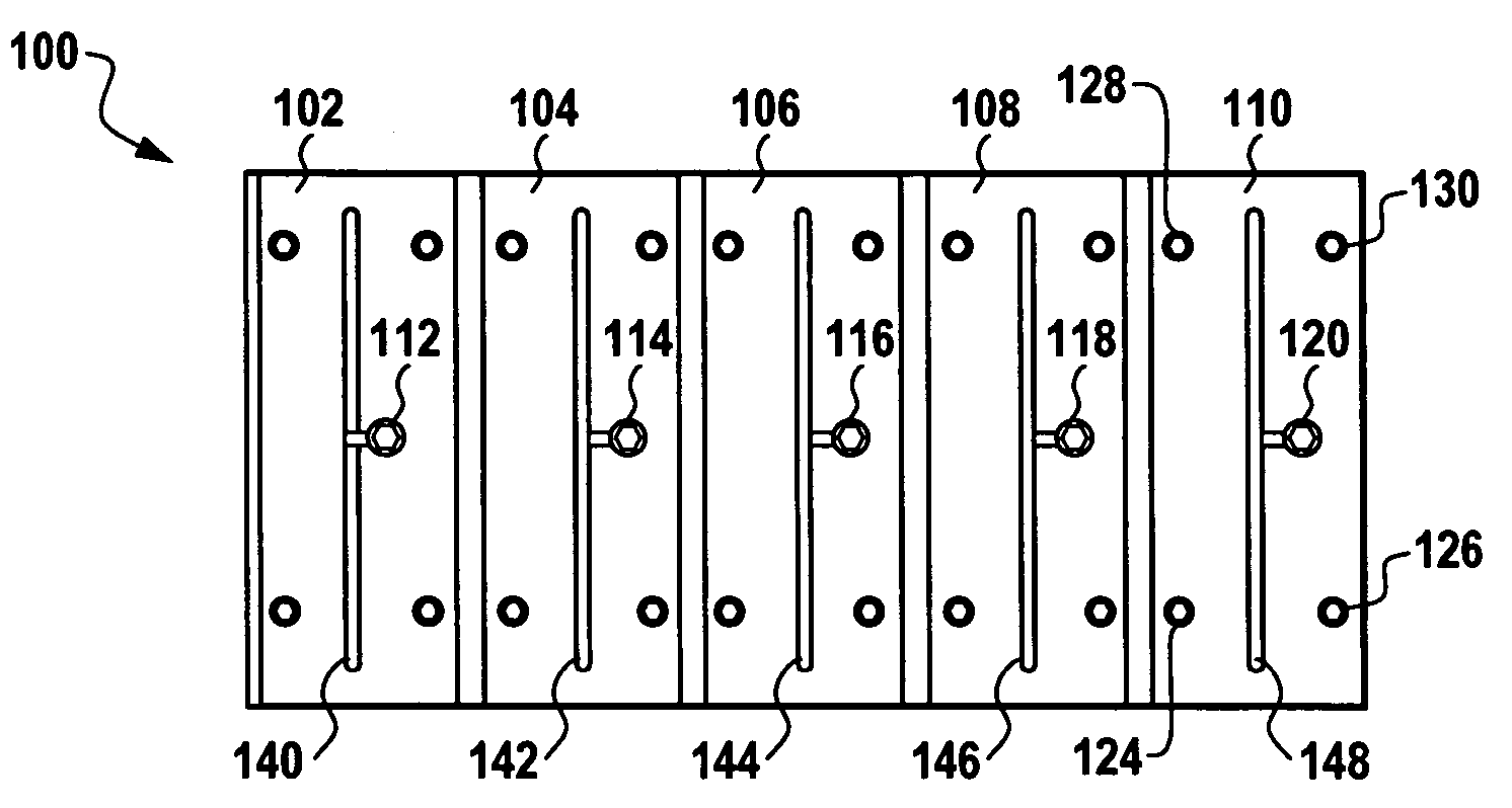
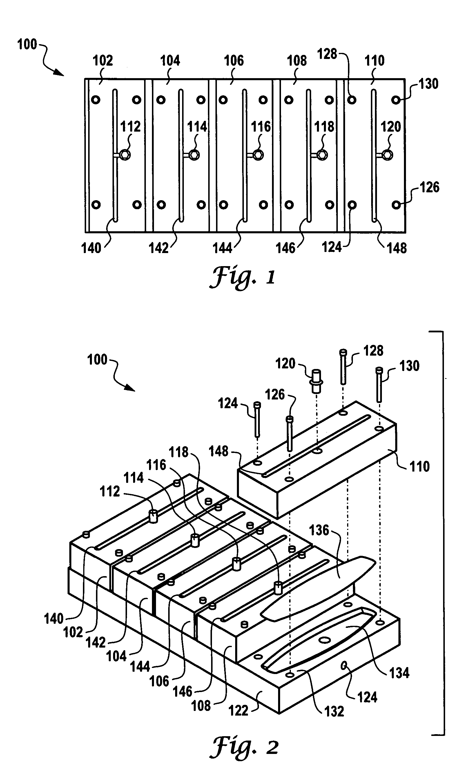
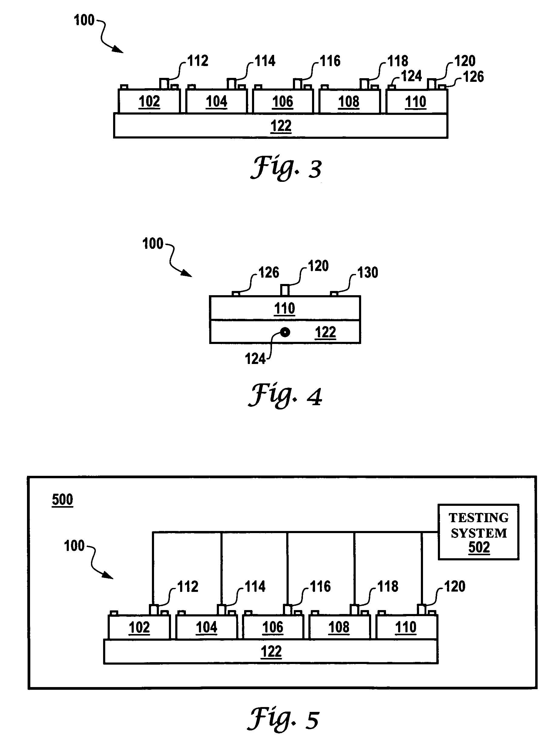
[0032]FIG. 1 illustrates a top view of a wireless sensor testing system 100, which can be implemented in accordance with an embodiment of the present invention. FIG. 2 illustrates a side perspective view of the wireless sensor testing system 100 depicted in FIG. 1, in accordance with an embodiment of the present invention. FIG. 3 illustrates a front view of the wireless sensor testing system 100 depicted in FIGS. 1-2, in accordance with an embodiment of the present invention. FIG. 4 illustrates a right side view of the wireless sensor testing system 100 depicted in FIGS. 1-3, in accordance with an embodiment of the present invention.

[0033] System 100 generally includes a pressure rail 122 upon which are disposed a plurality of antenna blocks...


PUM


Abstract

A wireless sensor fixture system and method are disclosed in which an antenna block is provided that includes a plurality of grooves, wherein such grooves maintain a plurality of antennas located on a portion of the antenna block. A top locator block can be positioned above the antenna block, wherein the top locator comprises a top surface having depression thereon for receiving and locating a patch, which can receives wireless signals from the antennas for sensor testing thereof, wherein the patch comprises a SAW sensor and an RFID tag over-molded into the patch. Additionally, an antenna cover can be connected to the antenna block for protecting the plurality of antennas and wiring thereof. A BNC connector protrudes from the antenna block and is electrically connected to the plurality of antennas via the wiring thereof.

Description

TECHNICAL FIELD [0001] Embodiments generally relate to sensing methods and systems. Embodiments are also related to pressure and temperature sensors. Embodiments are additionally related to surface acoustic wave (SAW) devices and sensors, and in particular to testing methods and systems thereof. Embodiments also relate to Radio Frequency Identification (RFID) Tags. BACKGROUND OF THE INVENTION [0002] Various sensors are known in the pressure and temperature sensing arts. The ability to detect pressure and / or temperature is an advantage to any devices which are under constant temperature and which can be severely affected by temperature conditions. An example of such a device is an automobile tire, which of course, experiences variations in both temperature and pressure. Many different techniques have been proposed for sensing the pressure and / or temperature in tires, and for delivering this information to the operator at a central location on the vehicle so that he knows that a tire ...

Claims


Application Information

Patent Timeline
Patent Type & Authority Applications(United States)
IPC IPC(8): G01D5/48G01D18/00
CPCG01D5/485G01D21/00G01D18/00
Inventor EISENHOWER, GARY W. JR.MARSH, BRIAN J.LARSON, ROGER L.
Owner HONEYWELL INT INC
Why Eureka
Try Eureka