Tensegrity joints for prosthetic, orthotic, and robotic devices

a technology of prosthetics and joints, applied in the field of prosthetics, orthotics, or robotic feet, can solve the problems of poor situation of people who lose a leg today, inability to walk up a grassy slope, and inability to overcome simple stairs. achieve the effect of elastic properties

Inactive Publication Date: 2005-09-29
TENSEGRITY PROSTHETICS
View PDF25 Cites 111 Cited by
  • Summary
  • Abstract
  • Description
  • Claims
  • Application Information

AI Technical Summary

Problems solved by technology

People who lose a leg today may be in a bad situation.
Some days, a simple staircase may seem like an insurmountable challenge.
Walking up a grassy slope is too difficult to attempt, because multiple falls may be inevitable.
War, accidents and disease keep this disadvantaged population growing.
Para-lympic records rivaling their Olympic counterparts show that the ESF paradigm works very well for running, but studies have failed to show that these benefits extend to walking.
Until recent, expensive innovation of computer controlled knees, AK amputees who wanted to walk faster than the return rate of their knee spring had to use a “hip snap,” flinging their prosthesis out quickly with their hip flexors, and then quickly contracting their hip extensors to snap the prosthetic knee straight in time for heel-strike.
The overuse of a particular muscle must result in overuse of the surrounding and supporting muscles.
Thus, putting a great deal of compression on the spine.
This is a well known pattern of muscle use and, if allowed to progress unchecked, may eventually result in degenerative joint changes in the lower spine.
As seen in the temporal gait asymmetry of amputees, most notably in late stance and swing phases, studies have shown conclusively that this action is not accomplished in either CF or ESF designs.
Amputees must rely exclusively on the strategy of top-down control, resulting in an overcompensation of the remaining anatomy which in turn may cause early degenerative changes.
A few studies have explored the detailed biomechanics of the foot using this powerful analytical technique, but they did not combine the detailed foot analysis with the protocol for the rest of the body.
Failure to accurately model the center of curvature of the leaf spring foot, for the purpose of reverse engineering the joint torques, may be the documented source of this error.
Studies of various prosthetic feet with the rollover profile methodology have shown that the “effective foot length” during walking is surprisingly short in many cases.
This correlates well with the experience of clinical prosthetists, who describe that their patients often work against their ESF feet, because their return of power is not biomechanically accurate.

Method used


Image

  • Tensegrity joints for prosthetic, orthotic, and robotic devices
  • Tensegrity joints for prosthetic, orthotic, and robotic devices
  • Tensegrity joints for prosthetic, orthotic, and robotic devices

Examples


example 1

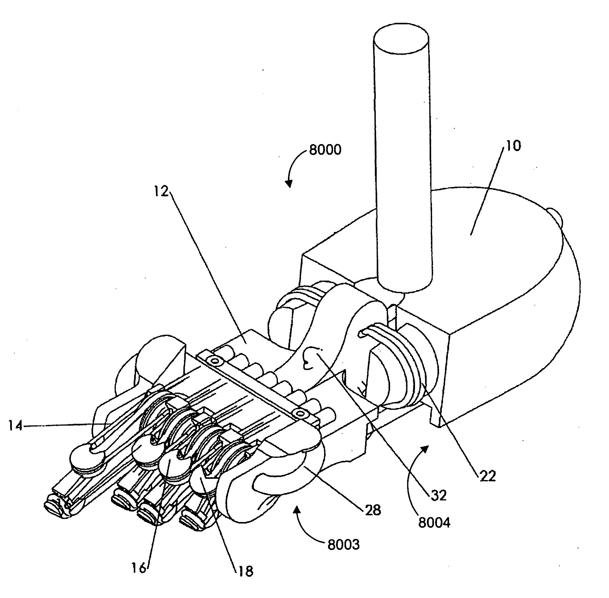
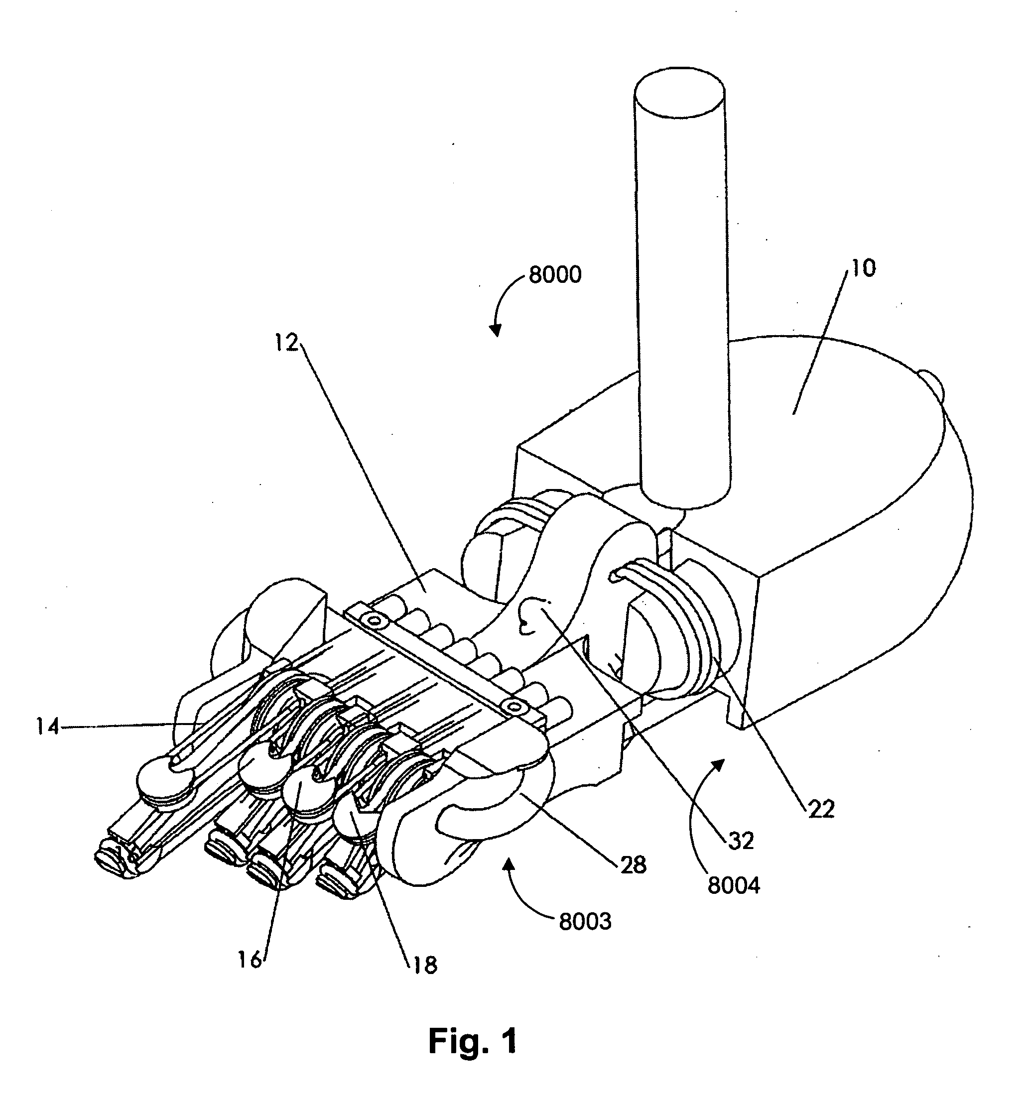
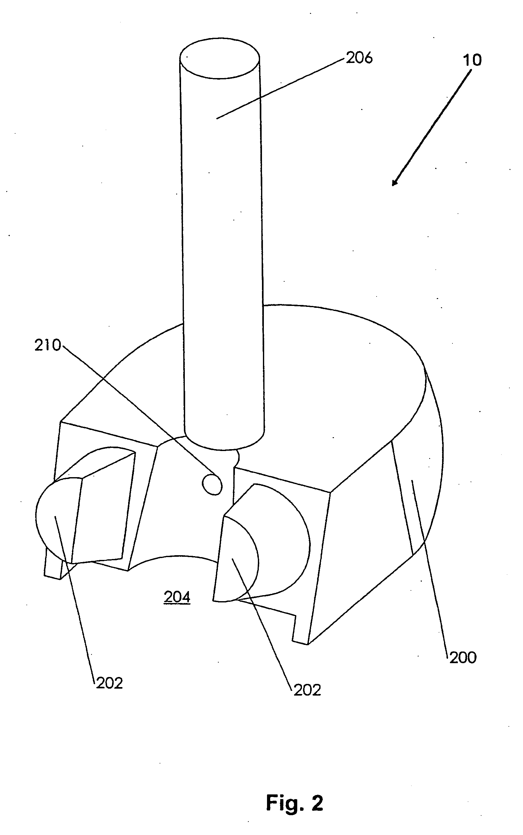
[0231] The prototype foot illustrated in FIGS. 1-10 may have been built using wood, brass, aluminum, plastic, yarn, and / or steel wire rope. It may be a right foot and may have one big toe, two medium toes, and one small toe.

example 2

[0232] The prototype orthotic boot illustrated in FIGS. 11-13 may have been built from wood, brass, aluminum, plastic, yarn, and / or steel wire rope cable. Several parts may be different from the foot illustrated in FIGS. 1-10. The boot may have four large toes, the midfoot joint attachment may be at about a 90-degree angle with the rest of the forefoot, and the parts on the outsides of the toes may be shorter.

example 3

[0233] The prototype ankle illustrated in FIGS. 14-17 may have been built using wood, brass, aluminum, plastic, yarn, and / or steel wire rope.


PUM


Abstract

Embodments of the invention relate to a prosthetic, orthotic, or robotic foot having at least two joints. One joint is located in a position analogous to the human MTP joint, and the other is located in a position analogous to the human subtalar joint. Motions of these two joints are mechanically couples. Furthermore, these joints are created using “tensegrity” design principals, where connections between the compression members are made by a network of tension members. These tension members create axes of motion, and limitations on those axes of motion. Actuators or linear elastic “springs” are use to alter the torque / angular deflection response curve of these joints, so that the rollover profile of the human foot can be duplicated by this invention.

Description

CROSS-REFERENCE TO RELATED APPLICATIONS [0001] The invention claims the benefit of priority of provisional U.S. Patent Application No. 60 / 553,619, filed Mar. 16, 2004, the entirety of which is incorporated herein by reference.DESCRIPTION OF THE INVENTION [0002] 1. Field of the Invention [0003] Embodiments of the present invention relate to a prosthetic, orthotic, or robotic foot that simulates the coordinated motions of the natural human foot in walking gait. More particularly, embodiments of the present invention relate to a prosthetic, orthotic, or robotic foot having three segments connected by two joints: one joint analogous to the human first metatarsophalangeal joint, and the other joint analogous to the human subtalar joint. The three segments correspond to a toe, a forefoot, and a heel. [0004] 2. Background of the Invention [0005] People who lose a leg today may be in a bad situation. Some days, a simple staircase may seem like an insurmountable challenge. Walking up a grass...

Claims


Application Information

Patent Timeline
Patent Type & Authority Applications(United States)
IPC IPC(8): A61F2/50A61F2/60A61F2/64A61F2/66
CPCA61F2/60A61F2/64A61F2/66A61F2002/5003A61F2002/6642A61F2002/6621A61F2002/6628A61F2002/6635A61F2002/5072
Inventor RIFKIN, JEROME
Owner TENSEGRITY PROSTHETICS
Why Eureka
Try Eureka