Body state estimation of a vehicle

a vehicle and body state technology, applied in the field of system and method of estimating body states of vehicles, can solve the problems of costly yaw rate and roll rate sensors

Inactive Publication Date: 2005-09-29
CONTINENTAL AUTOMOTIVE SYST INC
View PDF67 Cites 26 Cited by
  • Summary
  • Abstract
  • Description
  • Claims
  • Application Information

AI Technical Summary

Problems solved by technology

However, yaw rate and roll rate sensors are costly.

Method used


Image

  • Body state estimation of a vehicle
  • Body state estimation of a vehicle
  • Body state estimation of a vehicle

Examples


Embodiment Construction

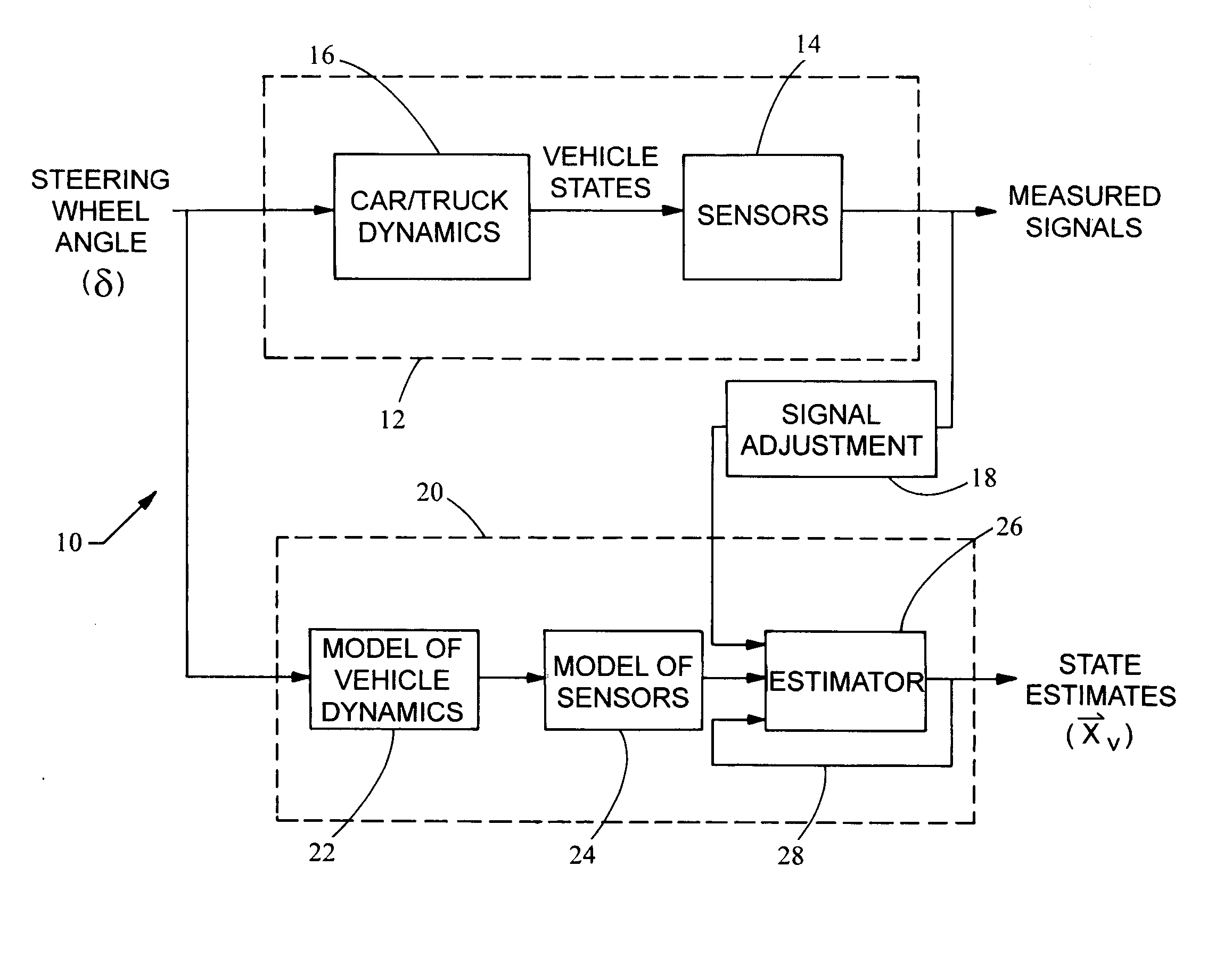
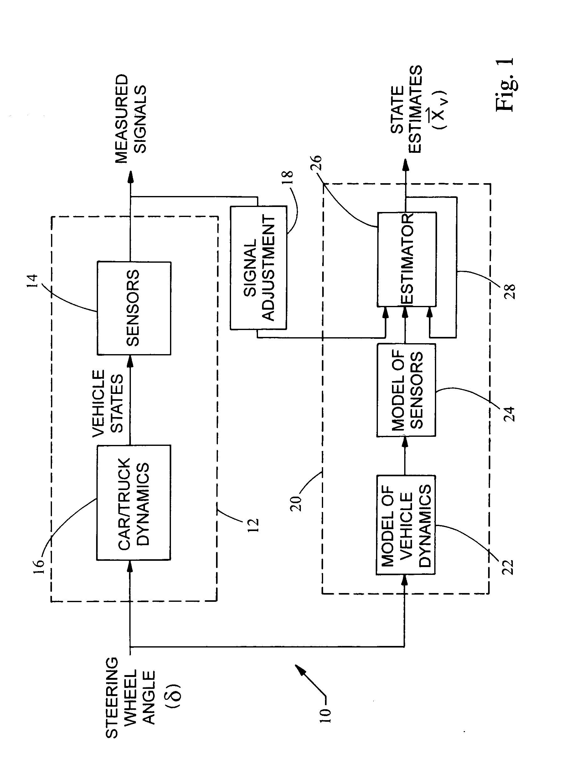
[0011] In accordance with an embodiment of the invention, FIG. 1 illustrates a system 10 that measures the vehicle states of a vehicle identified as block 12. Specifically, the system 10 includes a plurality of sensors 14 that measure signals which contain parts related to components of the vehicle states of the vehicle dynamics 16 produced, for example, when the angle of the steering wheel δ is changed.

[0012] The system 10 also includes a signal conditioner or adjuster 18 that receives measured signals from the sensors 14 and a filter 20 that receives the adjusted signals from the signal adjuster 18. In certain embodiments, the filter 20 is a Kalman filter including a model of the vehicle dynamics 22 and a model of the sensors 24. These models are described below in greater detail.

[0013] The signal adjuster 18 and the sensor model 24, which incorporates the model of the vehicle dynamics 22, provide inputs to an estimator 26. An algorithm with a feed back loop 28 is implemented in...


PUM


Abstract

The present invention features a system and method for estimating body states of a vehicle. The system includes at least two sensors mounted to the vehicle. The sensors generate measured vehicle state signals corresponding to the dynamics of the vehicle. A signal adjuster transforms the measured vehicle states from a sensor coordinate system to a body coordinate system associated with the vehicle. A filter receives the transformed measured vehicle states from the signal adjuster and processes the measured signals into state estimates of the vehicle, such as, for example, the lateral velocity, yaw rate, roll angle, and roll rate of the vehicle.

Description

BACKGROUND [0001] This invention relates to a system and method of estimating body states of a vehicle. [0002] Dynamic control systems have been recently introduced in automotive vehicles for measuring the body states of the vehicle and controlling the dynamics of the vehicle based on the measured body states. For example, certain dynamic stability control systems know broadly as control systems compare the desired direction of the vehicle based on the steering wheel angle, the direction of travel and other inputs, and control the yaw of the vehicle by controlling the braking effort at the various wheels of the vehicle. By regulating the amount of braking torque applied to each wheel, the desired direction of travel may be maintained. Commercial examples of such systems are known as dynamic stability program (DSP) or electronic stability program (ESP) systems. [0003] Other systems measure vehicle characteristics to prevent vehicle rollover and for tilt control (or body roll). Tilt c...

Claims


Application Information

Patent Timeline
Patent Type & Authority Applications(United States)
IPC IPC(8): B60W30/04B60R16/02B60T8/172B60W30/00B60W40/10B60W40/12B60W50/00G06F19/00
CPCB60T2250/03B60T8/172
Inventor BAUER, GEOFFREY BURKELEHMANN, KURT STOUFFERHILDEBRAND, BRIAN L.SCHUMANN, CLINTON
Owner CONTINENTAL AUTOMOTIVE SYST INC
Why Eureka
Try Eureka