System and method for dynamically determining vehicle loading and vertical loading distance for use in a vehicle dynamic control system

a dynamic control system and vehicle technology, applied in the direction of pedestrian/occupant safety arrangement, cycle equipment, instruments, etc., can solve the problems of more than 30% error in relative roll angle calculation, inability to achieve optimal control performance, and variation of the relative roll angle, etc., to achieve the effect of very accurate determination

Inactive Publication Date: 2010-02-23
FORD GLOBAL TECH LLC
View PDF373 Cites 23 Cited by
  • Summary
  • Abstract
  • Description
  • Claims
  • Application Information

AI Technical Summary

Benefits of technology

[0016]One advantage of the invention is that various vehicle loading conditions can be detected and determined very accurately. Such is true even though vehicle loading conditions (for example, roof loadings) are usually a fraction of a vehicle's total mass (for example, 3% to 6% of the vehicle's curb weight), are difficult to detect when using methods largely involving longitudinal vehicle dynamics, and may cause large (for example, more than 30%) changes in the vehicle's chassis roll angle.
[0017]Other advantages and features of the present invention will become apparent when the detailed written description of a preferred embodiment of the invention set forth below is viewed in conjunction with both the attached drawing figures and the appended claims.

Problems solved by technology

One problem with using these parameters in the computation is that the aforementioned relative roll angle may vary with the vehicle operating conditions.
For example, a 150 pound roof loading for a typical SUV with a curb weight of 5000 pounds may cause more than 30% error in relative roll angle calculations if computed assuming no roof load.
If the above parameters are fixed at certain nominal values in the RSC system, it is conceivable that optimal control performance may not be achieved under a different loading condition.
For example, if the relative roll angle is computed with nominal vehicle loading condition assumptions, without considering roof loading, the relative roll angle may be under estimated for vehicles with roof loadings, which results in a reduced control.
That is, the control system may not be as effective as desired.
On the other hand, if the relative roll angle is computed with maximum roof loading, it may be over estimated for vehicles without roof loadings causing unintended control.
That is, the control system may become too sensitive or intrusive.
The mass estimation schemes proposed in the above-cited patents may not accurately indicate changes to parameters that impact the roll dynamics of the vehicle.
For example, a 150 pound roof loading on a 5000 pound SUV, i.e., 3% mass change, might be undetectable in the above schemes due to the potential error in the engine torque, which usually is much larger than 3%.
Other error sources include the road grade, the tire rolling radius change due to tire pressure drop and due to the vehicle loading variations and the vehicle drag.
However, in our case, the roof loading causes much more significant roll motion parameter changes than does the same amount of floor loading.
That is, the prior art does not address vehicle inertia and mass properties with respect to the vehicle body roll and lateral dynamics.
The estimation methodologies suggested in the literature have been considering the vehicle longitudinal dynamics and are not appropriate for an RSC system where the lateral and roll dynamics are more important than longitudinal dynamics.
Furthermore, the other parameters that affect vehicle body roll and lateral dynamics, such as the roll stiffness and damping in the suspensions and the total center of gravity height of the vehicle body with respect to the vehicle floor, the roll moment of inertia, have not been estimated and / or considered in the prior art.

Method used


Image

  • System and method for dynamically determining vehicle loading and vertical loading distance for use in a vehicle dynamic control system
  • System and method for dynamically determining vehicle loading and vertical loading distance for use in a vehicle dynamic control system
  • System and method for dynamically determining vehicle loading and vertical loading distance for use in a vehicle dynamic control system

Examples


Embodiment Construction

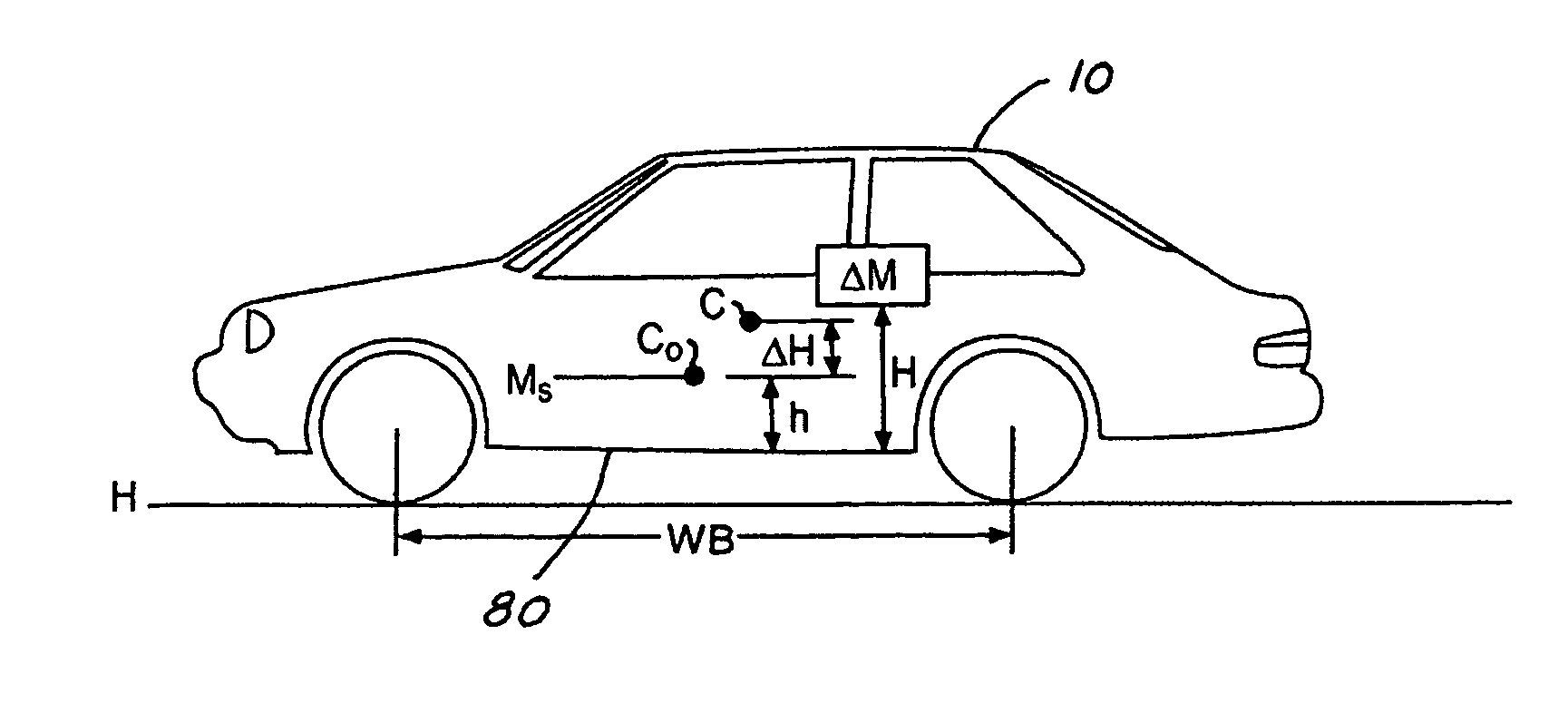
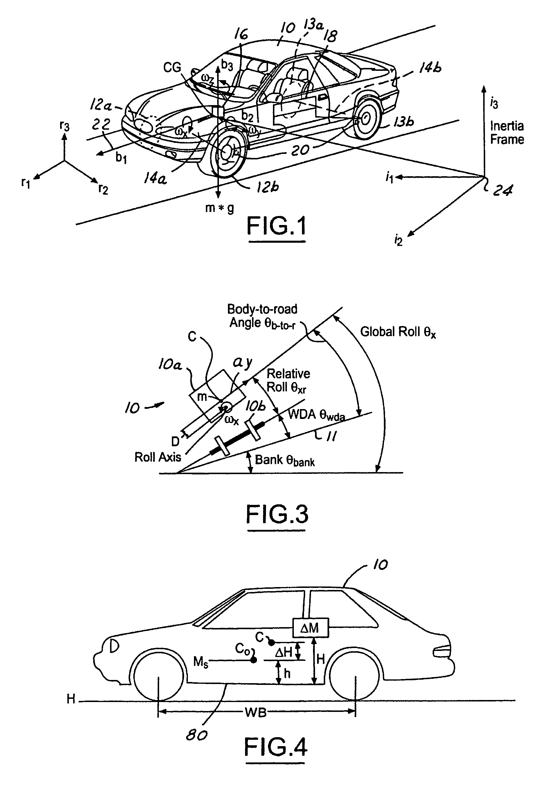
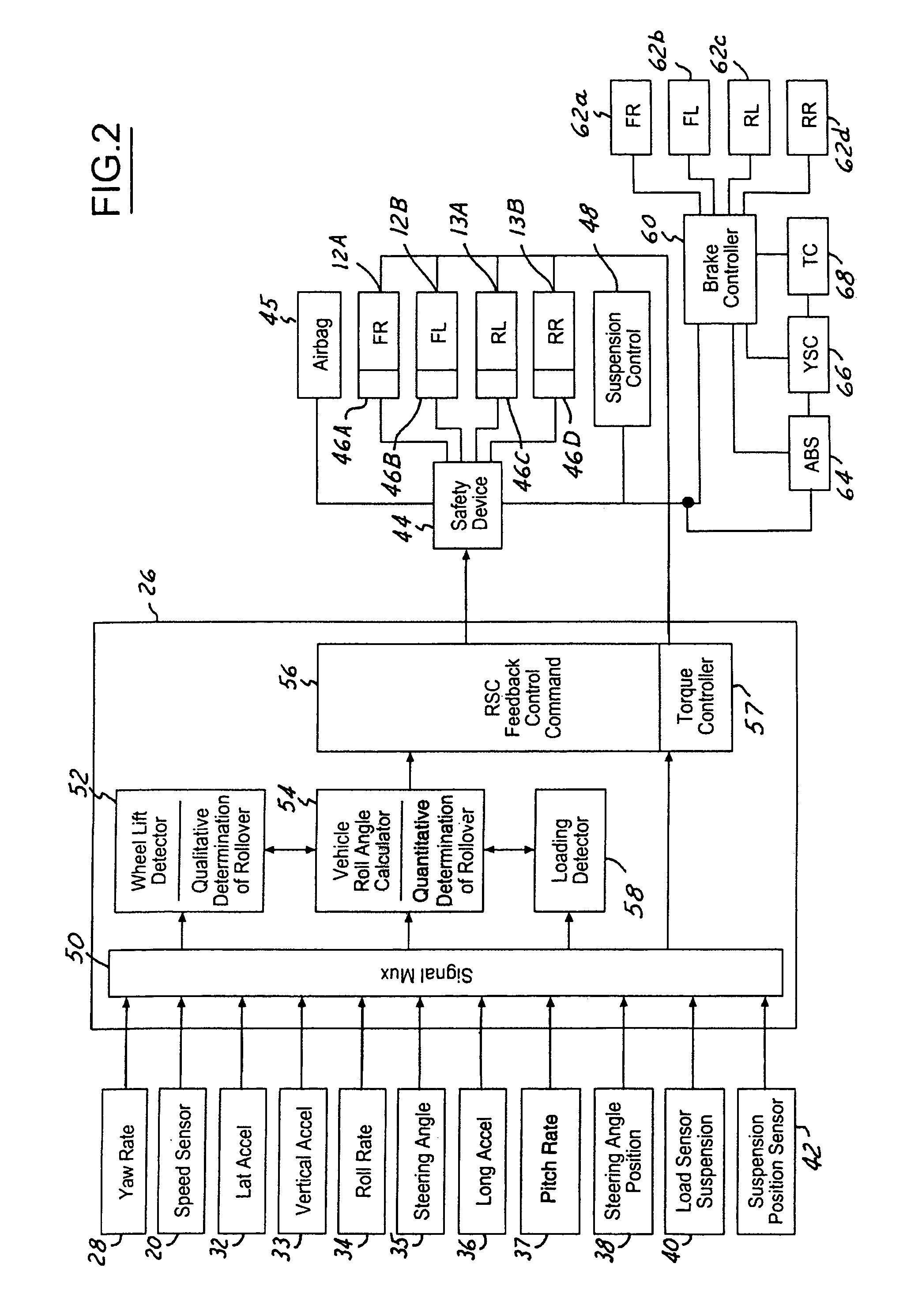
[0026]In the following figures, the same reference numerals will be used to identify the same components. The present invention may be used in conjunction with a rollover control system for a vehicle. The present invention may also be used with a deployment device such as an airbag or active roll bar. The present invention will be discussed below in terms of preferred embodiments relating to an automotive vehicle moving in a three-dimensional road terrain. The present invention is described with respect to determining an added mass and height of the mass. As will be described below the added mass and height may not be directly determined, rather by adaptively updating a roll gradient value, roll acceleration coefficient, roll moment of inertia and / or a roll rate coefficient, the effects of added mass and the height may be included in those values. Such values may also be referred to as an “adaptive” roll gradient, an “adaptive” roll acceleration coefficient, an “adaptive” roll momen...


PUM


Abstract

A control system (18) and method for an automotive vehicle (10) includes a roll rate sensor (34) for generating a roll rate signal, a lateral acceleration sensor (32) for generating a lateral acceleration signal, a longitudinal acceleration sensor (36) for generating a longitudinal acceleration signal, and a yaw rate sensor (28) for generating a yaw rate signal. A safety device or system (44) and the sensors are coupled to a controller. The controller (26) determines an added mass and the height of the added mass on the vehicle, or a roll gradient, a roll acceleration coefficient, and / or a roll rate parameter that take into account the added mass and height from the roll rate, the lateral acceleration, the longitudinal acceleration, and the yaw rate of the vehicle, and controls the safety system in response thereto.

Description

TECHNICAL FIELD[0001]The present invention generally relates to a control apparatus for controlling a system of an automotive vehicle in response to sensed dynamic behavior. The present invention more specifically relates to a method and apparatus for determining vehicle loading and a vertical loading distance and / or the impact of such vehicle loading on the roll dynamics of the vehicle.BACKGROUND[0002]Recently, vehicle roll stability control (RSC) schemes, i.e., U.S. Pat. No. 6,324,446, have been proposed to address the issue of friction-induced rollovers. RSC system includes a variety of sensors sensing vehicle states and a controller that controls a distributed brake pressure to reduce a tire force so the net moment of the vehicle is counter to the roll direction.[0003]During an event causing the vehicle to roll, the vehicle body is subject to a roll moment due to the coupling of the lateral tire force and the lateral acceleration applied to the center of gravity of the vehicle b...

Claims


Application Information

Patent Timeline
Patent Type & Authority Patents(United States)
IPC IPC(8): B60R21/0132B60R21/00B60T8/1755B60T8/24B60W10/18B60W10/22B60W30/04B60W40/10
CPCB60R21/0132B60T8/17551B60T8/24B60T8/241B60W30/04B60W40/10B60G17/016B60G2800/0124B60G2800/0194B60G2800/915B60R2021/0018B60T2230/03B60T2250/02B60W10/18B60W10/22B60W40/072B60W40/076B60W40/13B60W2520/18B60W2550/142B60W2720/18B60G2400/61B60W2552/15B60G2800/019
Inventor LU, JIANBOMATTSON, KEITHMESSIH, DAVIDCHUBB, ERIKSALIB, ALBERT
Owner FORD GLOBAL TECH LLC
Why Eureka
Try Eureka