Method and circuit arrangement for testing electrical modules

Inactive Publication Date: 2005-09-29
POLARIS INNOVATIONS
View PDF17 Cites 11 Cited by
  • Summary
  • Abstract
  • Description
  • Claims
  • Application Information

AI Technical Summary

Benefits of technology

[0013] However, it may also be desirable to test the so-called “integrity” (physical correctness) of the signals supplied by the test specimens, i.e., the form fidelity of the temporal profile of the signals. Testing the form fidelity of the signals is not only expedient when testing analog circuits but is also gaining increasing importance for testing digital modules. Even present-day digital modules operate at frequencies that are close to the limit of what can be handled by transmission lines. Thus, small deviations in the signal form of the output signal of a digital module (e.g., in the edge steepness or in the peak voltage of a data pulse) may have the effect that the signal is no longer reliably identified at the end of a transmission link even though it appears “logically correctly” at the output of the module. This may lead to malfunctions of an overall system in which the relevant module is inserted. Since the commercial testers available nowadays for digital circuits can only test the logical correctness, such malfunctions can only be found by performing tests within the overall system, that is to say, on the system board or motherboard after the module has been inserted into the system (so-called “motherboard” test). This is disadvantageous because a module identified as defective has to be separated from the system again and replaced by a new module.
[0014] In a particular embodiment of the invention, measures are taken to test the physical integrity of the output signals of the test specimens. For this purpose, the test com

Problems solved by technology

This reduces the test device outlay and

Method used


Image

  • Method and circuit arrangement for testing electrical modules
  • Method and circuit arrangement for testing electrical modules
  • Method and circuit arrangement for testing electrical modules

Examples


Embodiment Construction

[0023] The invention relates to a method and a circuit arrangement for testing electrical modules. Unless defined in greater detail, the general term “module” here is taken to mean electrical circuits or assemblies of any desired type. A preferred, but not exclusive, field of application for the invention is in electronic modules that are formed as integrated circuits on a semiconductor chip, in particular data memories. One particular embodiment provides a data memory circuit specifically designed for an application of the test method according to the invention.

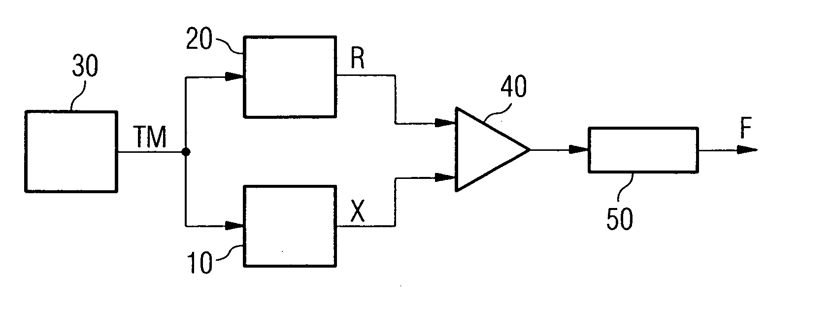
[0024] In FIG. 1, the block 10 symbolizes a “test specimen”, that is to say, an electrical module to be tested, which may be of arbitrary type and the useful function of supplying respectively prescribed output signals as a response to defined input signals. To test whether or to what extent the test specimen 10 correctly fulfills this function, a test pattern TM of input signals is applied to the test specmen 10. The test ...


PUM


Abstract

The invention relates to a method for testing electrical modules. A test pattern of input signals is applied to each module to be tested as test specimen, and the actual responses of the test specimen to the test pattern is compared with the desired responses. The comparison result is evaluated for the purpose of displaying test assessments. According to one embodiment of the invention, to supply the desired responses, a reference module produced with the same design and technology as the test specimen and tested as entirely satisfactory is utilized. The same test pattern as for the test specimen is applied to the reference module. The invention furthermore relates to circuit arrangements for carrying out this method, in particular for testing data memories.

Description

CROSS-REFERENCE TO RELATED APPLICATIONS [0001] This application claims foreign priority benefits under 35 U.S.C. §119 to co-pending German patent application number DE 10 2004 010 783.1-35, filed 5 Mar. 2004. This related patent application is herein incorporated by reference in its entirety. BACKGROUND OF THE INVENTION [0002] 1. Field of the Invention [0003] The invention relates to a method and a circuit arrangement for testing electrical modules. A preferred, but not exclusive, field of application for the invention is in electronic modules that are formed as integrated circuits on a semiconductor chip, in particular data memories. Thus, the invention relates, in a particular embodiment, to a data memory circuit specifically designed for an application of the test method according to the invention. [0004] 2. Description of the Related Art [0005] Electrical modules are generally tested by a test pattern of input signals being applied to the modules as “test specimens” and output s...

Claims


Application Information

Patent Timeline
IPC IPC(8): G01R31/28G01R31/3185G01R31/319G01R31/3193G06F11/00G11C29/00G11C29/38
CPCG01R31/318505G01R31/31917G11C2029/0401G11C29/38G01R31/3193
Inventor POECHMUELLER, PETER
Owner POLARIS INNOVATIONS
Why Eureka
Try Eureka