
Combined gas flow generator & control valve housing in a ventilator

a technology of control valve and gas flow generator, which is applied in the field of ventilators, can solve the problems of unnecessarily bulky conventional ventilators, and achieve the effect of convenient insertion or removal

Inactive Publication Date: 2005-10-06
BREAS MEDICAL
View PDF6 Cites 22 Cited by
  • Summary
  • Abstract
  • Description
  • Claims
  • Application Information

AI Technical Summary

Benefits of technology

[0011] It is the object of the present invention to provide a more compact ventilator compared to currently available ventilators on the market, as well as to reduce the overall manufacturing cost of the ventilator. SUMMARY OF THE INVENTION
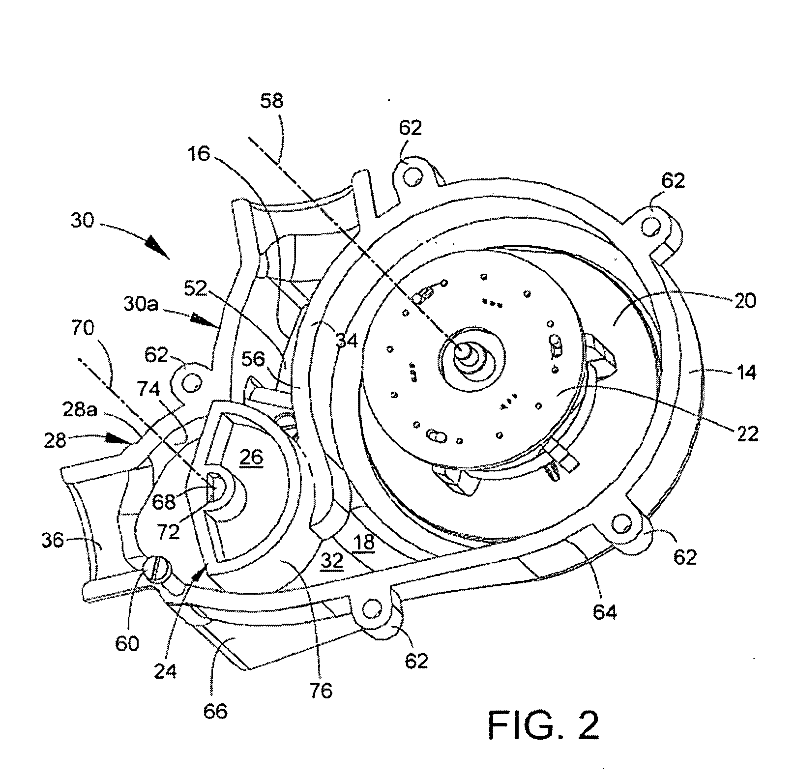
[0014] a control valve for controlling the flow and / or pressure of the gas distributed to the patient, said control valve comprising a valve body which is movably arranged within a valve chamber wherein, said gas flow generator chamber and said valve chamber are integrally formed in a combined gas flow generator & control valve housing; said valve chamber is located in immediate conjunction to the gas outlet opening of the gas flow generator chamber within said combined gas flow generator & valve housing and said valve body comprise transitions portions for providing smooth pressure and / or flow transitions during transitions between closed and open positions of the valve body.
[0020] Advantageously, an electric stepper motor is attached to the combined gas flow generator & control valve housing. The electric stepper motor has a stepper motor shaft coupled to the valve body in said valve chamber. Furthermore, the valve body is provided with a through hole, said through hole having a cross-sectional shape such that the valve body is rotationally fixed relative to the stepper motor shaft, whilst being freely slidably arranged in an axial direction of said stepper motor shaft for easy insertion or removal of the valve body in the valve chamber.

Problems solved by technology

Hence, partly for this reason, conventional ventilators tend to be unnecessarily bulky.

Method used


Image

  • Combined gas flow generator & control valve housing in a ventilator
  • Combined gas flow generator & control valve housing in a ventilator
  • Combined gas flow generator & control valve housing in a ventilator

Examples


Embodiment Construction

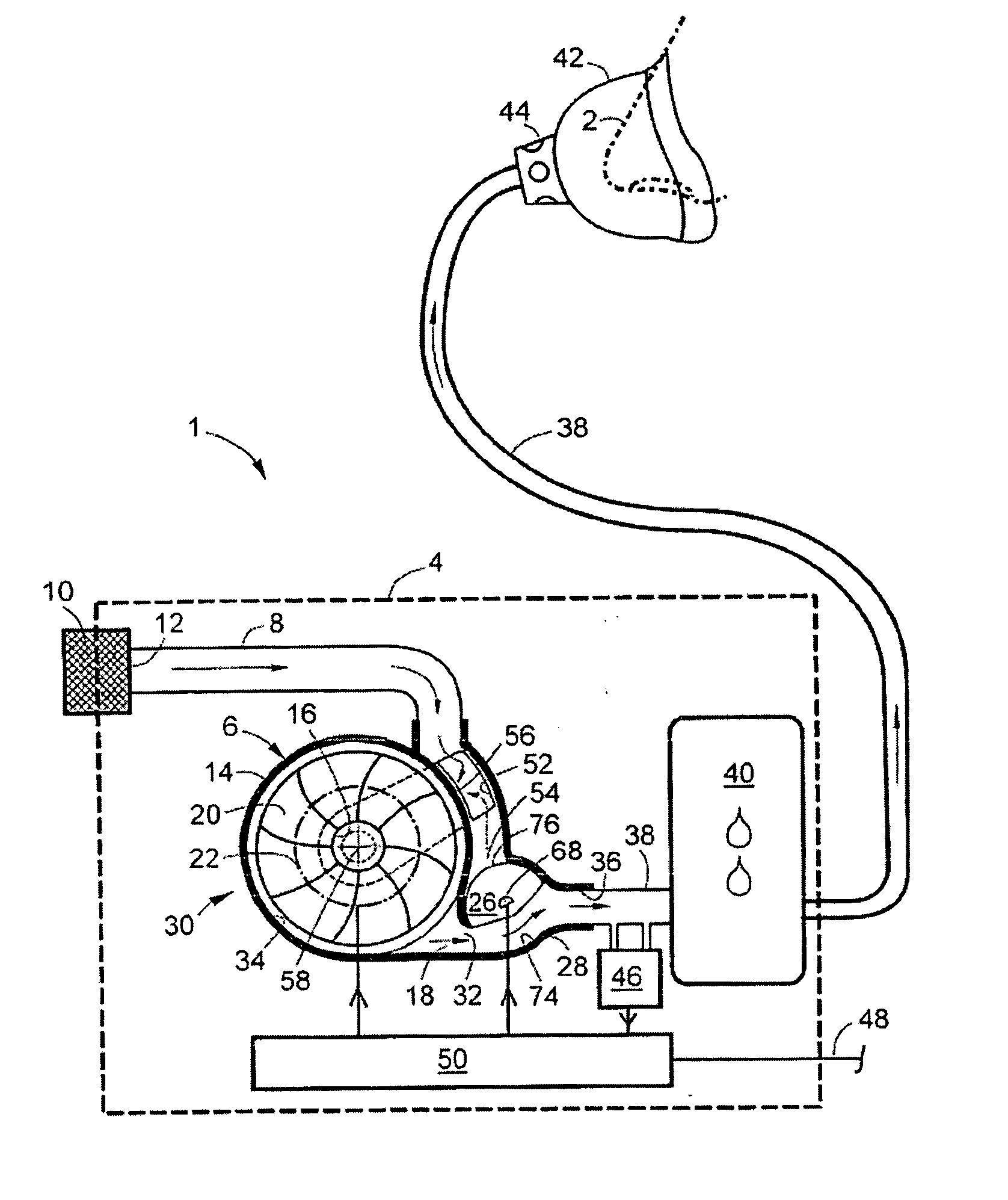
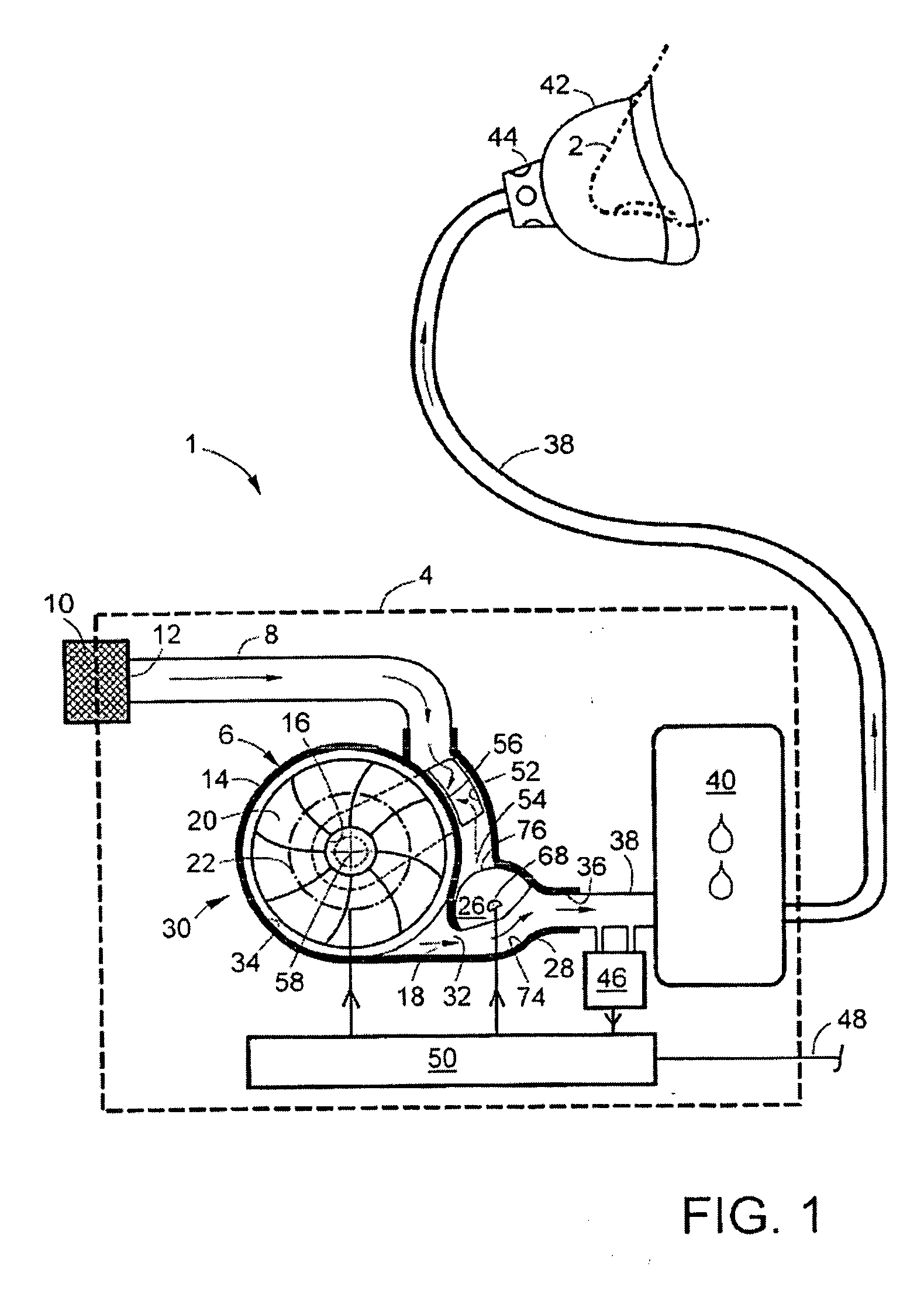
[0029] In FIG. 1, reference numeral 1 denotes a ventilator for supplying breathable gas—normally air—into the airway of a patient for treating breathing disorders such as for example Obstructive Sleep Apnea (OSA), Cheyne-Stokes respiration or emphysema. In the figure, a schematically drawn nose 2 of a patient is shown with dash-dotted lines. It should be noted that the schematic FIG. 1 is drawn in a highly simplified way in order to clearly illustrate the basic features of the invention. Thus, a production version of a ventilator according to the invention may look significantly different than in the shown illustrations, although the basic features are still present.

[0030] As mentioned in the background above, the ventilator is either of the initially described Bi-Level CPAP type or the AutoCPAP-type.

[0031] The ventilator 1 has an external housing 4, schematically illustrated with dashed lines in FIG. 1. A gas flow generator 6 is located within the external housing 4. In the prefe...


PUM


Abstract

A ventilator for supplying breathable gas to the airway of a patient with a respiratory disorder, comprising: a gas flow generator, such as an electric fan, for generating a flow of said breathable gas to the patient, said gas flow generator comprising a gas flow generator chamber provided with a gas inlet opening and a gas outlet opening; a control valve for controlling the flow and / or pressure of the gas distributed to the patient, said control valve comprising a valve body which is movably arranged within a valve chamber, wherein said gas flow generator chamber and said valve chamber are integrally formed in a combined gas flow generator & control valve housing; said valve chamber is located in immediate conjunction to the gas outlet opening of the gas flow generator chamber within said combined gas flow generator & valve housing; and said valve body comprise transitions portions for providing smooth pressure and / or flow transitions during transitions between closed and open positions of said control valve.

Description

CROSS REFERENCE TO RELATED APPLICATION [0001] This application claims priority from Swedish Patent Application 0400891-8 filed on Apr. 5, 2004 and U.S. Provisional Patent Application Ser. No. 60 / 573,230, filed on May 21, 2004.FIELD OF THE INVENTION [0002] The present invention relates to a ventilator for supplying breathable gas, normally air, at elevated pressure to a patient for treating breathing disorders such as for example Obstructive Sleep Apnea (OSA), Cheyne-Stokes respiration or emphysema. The ventilator may also be used in the treatment of cardiac disorders, such as Congestive Heart Failure (CHF). The invention is applicable to advanced intensive care ventilators for assisted ventilation or Continuous Positive Airway Pressure ventilators (CPAP). More particularly, the ventilator comprises a novel compact design feature, which substantially reduces the overall size of the ventilator, thus improving user comfort for the patients. BACKGROUND OF THE INVENTION [0003] Ventilator...

Claims


Application Information

Patent Timeline
Patent Type & Authority Applications(United States)
IPC IPC(8): A61M16/00A61M16/16A61M16/20A62B7/00
CPCA61M16/0057A61M16/0066A61M16/204A61M16/20A61M2016/0039A61M16/16A61M16/0069A61M16/107
Inventor BENGTSSON, STAFFANLJUNGBERG, LARSNILSSON, MATSTIEDJE, MIKAEL
Owner BREAS MEDICAL
Learn More