Wet friction material

a friction material and wet technology, applied in the direction of friction lining, mechanical actuated clutches, braking discs, etc., can solve the problems of hydraulic oil drag torque generation, limited oil passage area of segment-type friction material, and difficult to discharge the remaining lubricating oil between the segment-type friction material and the separator plate, etc., to reduce the drag torque sufficiently, reduce the cost, and manufacture in a short period of time

Active Publication Date: 2005-10-06
AISIN CHEM CO LTD
View PDF10 Cites 23 Cited by
  • Summary
  • Abstract
  • Description
  • Claims
  • Application Information

AI Technical Summary

Benefits of technology

[0008] An object of the present invention is to provide a wet friction material that reduces a drag torque sufficiently even at a portion where a lubricating oil remains in a great quantity and is hard to be discharged and that can be manufactured in a short period of time so as to lower costs.
[0014] It is preferable that the constant angle is about 45 degrees. In this case, if the first oil grooves and the second oil grooves are provided in the same number and alternately disposed, the largest drag torque reduction effect is obtained.
[0016] It is preferable that a proportion of the height of the symmetrical broadened portion of the first oil groove to the total height of the first oil groove is about 30%. In this case, if the first oil grooves and the second oil grooves are provided in the same number and alternately disposed, the largest drag torque reduction effect is obtained.
[0023] In case of the segment-type friction material, the segment piece may be a large one with a large width (radial size) corresponding to an entire width of the ring shape portion of the core metal and a large length (circumferential size). In this case, the number of the segment pieces can be reduced, so that a time for cutting off and joining of the segment pieces is shortened and the costs can be reduced. On the other hand, the press-type friction material can be manufactured only by joining the friction material substrate on one or both surfaces of the ring shape portion of the core metal and pressing it from one or both sides. Therefore, it is suitable for mass-production, thereby reducing the costs.

Problems solved by technology

Moreover, a total area of an oil passage provided on the segment-type friction material is restricted in order to assure a sufficient torque transmission capacity at the time of clutching operation of the hydraulic clutch.
Consequently, it is hard to discharge the lubricating oil remaining between the segment-type friction material and the separator plate at the time of clutching operation of the hydraulic clutch.
As a result, there was a problem that a drag torque was generated by the hydraulic oil caused by a relative rotation of both the plates.
Therefore, there is a problem that the drag torque is not reduced enough by the lubricating oil, though it involves effort to produce and increases costs.

Method used


Image

  • Wet friction material
  • Wet friction material
  • Wet friction material

Examples


first embodiment

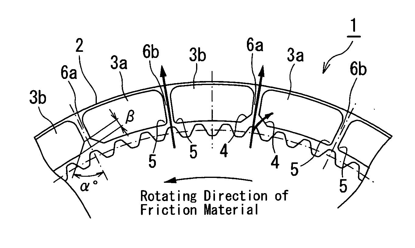
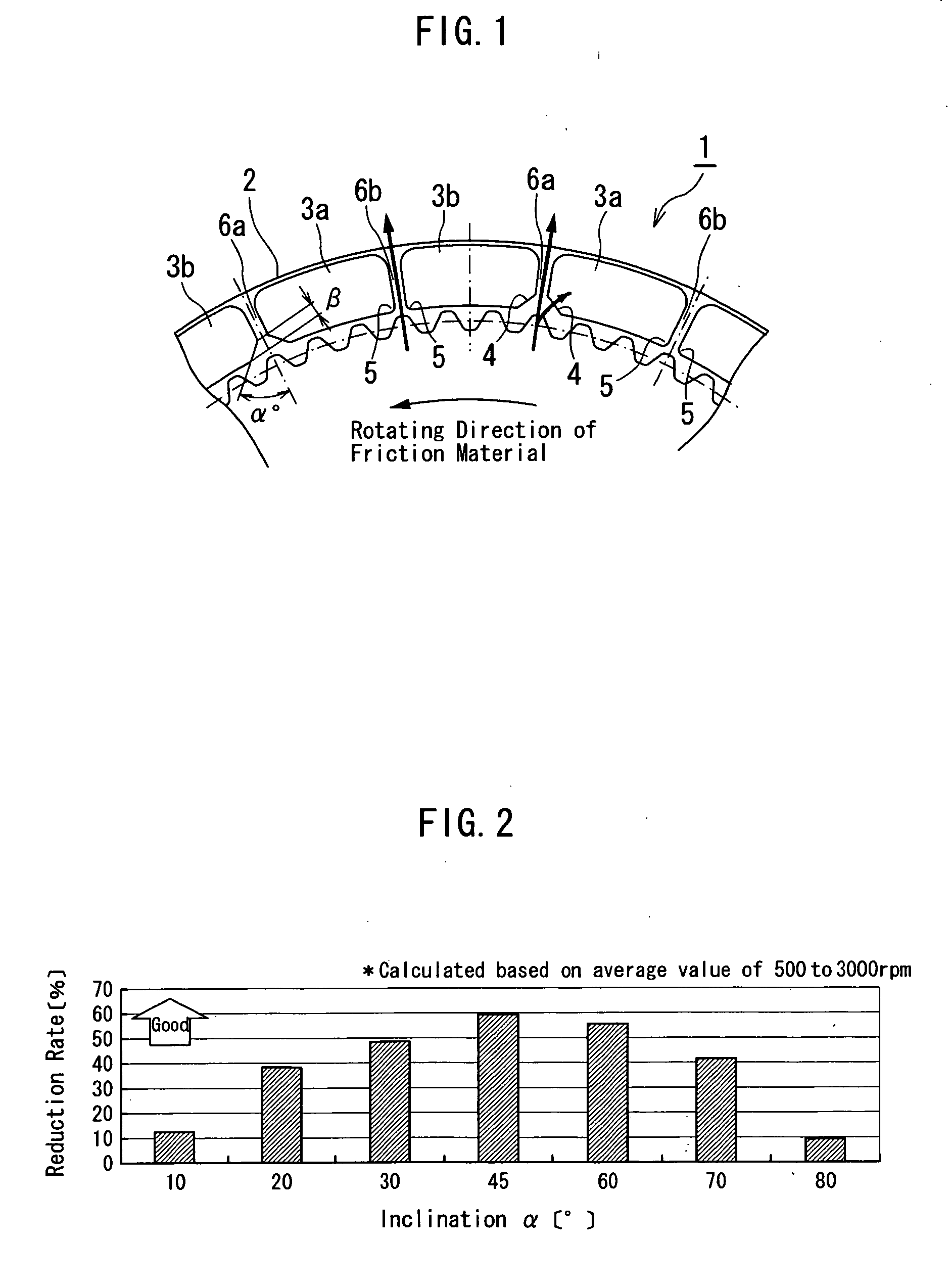
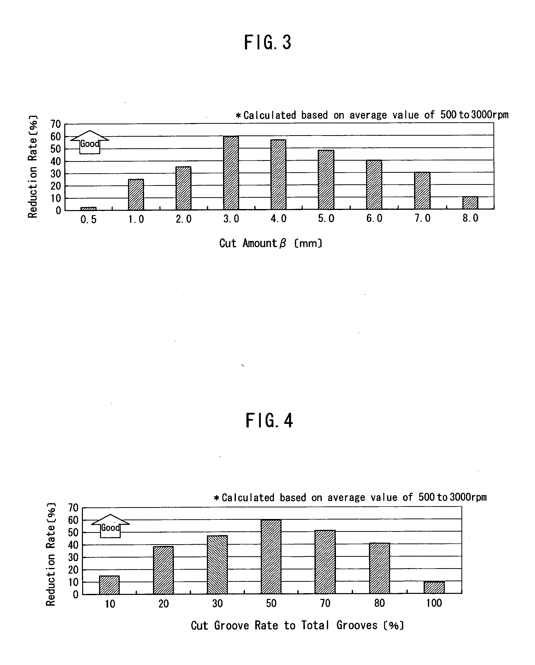
[0037] A first embodiment of a wet friction material is described referring to FIG. 1 to FIG. 5. FIG. 1 is a plan view showing a part of a wet friction material according to a first embodiment of the invention. FIG. 2 is a graph showing a relation between an inclination angle of an inner peripheral corner of an oil groove and a drag torque reduction rate in the wet friction material according to the first embodiment of the invention. FIG. 3 is a graph showing a relation between a height of an inclined part of the inner peripheral corner of the oil groove and the drag torque reduction rate in the wet friction material according to the first embodiment of the invention. FIG. 4 is a graph showing a relation between a proportion of a number of the oil grooves with the inclined inner peripheral corner to a total number of all the oil grooves and the drag torque reduction rate in the wet friction material according to the first embodiment of the invention. FIG. 5 is a graph showing a rela...

second embodiment

Modified Examples of Second Embodiment

[0058] Next, a segment-type friction material as a wet friction material according to a first modified example of the second embodiment is described referring to FIG. 7. As shown in FIG. 7, the first modified example of the second embodiment of the segment-type friction material 11B has no inner peripheral side of a segment piece cut off contrary to the segment-type friction material 1 or the segment-type friction material 11A described heretofore. Center portions or dents 24 in a radial direction of the segment piece 23a, 23b, which are faced to each other across the oil groove 16a, are respectively cut off in a symmetrical manner.

[0059] In case the segment pieces 23a, 23b have the center portions 24 or the broadened portions not at the inner peripheral side but at the center of the oil groove 16a, similar effects are obtained. That is, in case the segment-type friction material 11B is assembled in an automatic transmission (AT), when the fric...


PUM


Abstract

In a segment-type wet friction material, an inner peripheral left corner of one segment piece and an inner peripheral right corner of another segment piece are respectively cut off at a fixed angle to a center line of an oil groove. The oil grooves have first oil grooves and second oil grooves. The second oil groove has nearly a uniform width. The first oil groove has an inner peripheral corner portion that is broadened to the center line of the oil groove from a fixed height. In case of being assembled in an automatic transmission, when the segment-type friction material rotates in one direction, an automatic transmission fluid supplied from an inner circumference bumps and touches the portion that is broadened at the fixed angle at a rear side in the rotating direction. Thus, the automatic transmission fluid is positively supplied to a friction surface of the segment piece so as to restrain a contact between a separator plate and the friction surface. Consequently, excess automatic transmission fluid is discharged from the second oil groove, thereby reducing largely a drag torque by the automatic transmission fluid.

Description

BACKGROUND OF THE INVENTION [0001] 1. Field of the Invention [0002] This invention relates to a wet friction material that generates a torque by applying a high pressure to an opposite surface while being immersed in an oil. In detail, this invention relates to a segment-type friction material made by joining friction material substrates that were cut into a segment piece onto one or both of opposite surfaces of a core metal of a flat ring shape along an entire circumference thereof with an adhesive. Otherwise, this invention relates to a press-type friction material made by pressing one or both of opposite surfaces of a friction material that has friction material substrates joined onto one or both of opposite surfaces of a core metal of a flat ring shape along an entire circumference thereof with an adhesive so as to form a plurality of oil grooves in a radial direction. [0003] 2. Description of the Related Art [0004] In recent years, a segment-type friction material 21 as shown i...

Claims


Application Information

Patent Timeline
Patent Type & Authority Applications(United States)
IPC IPC(8): F16D13/62F16D13/64F16D13/72F16D65/12F16D69/00
CPCF16D13/64F16D65/127F16D2069/0491F16D13/648F16D2069/004F16D25/123
Inventor MURANAKA, TAKUYASUGIURA, TAKATORASUZUKI, MASATO
Owner AISIN CHEM CO LTD
Why Eureka
Try Eureka