

Vehicle front body structure
- Summary
- Abstract
- Description
- Claims
- Application Information
AI Technical Summary
Benefits of technology
Problems solved by technology
Method used
Image

Examples
Embodiment Construction
[0017] An embodiment of the present invention will be explained below with reference to the drawings.
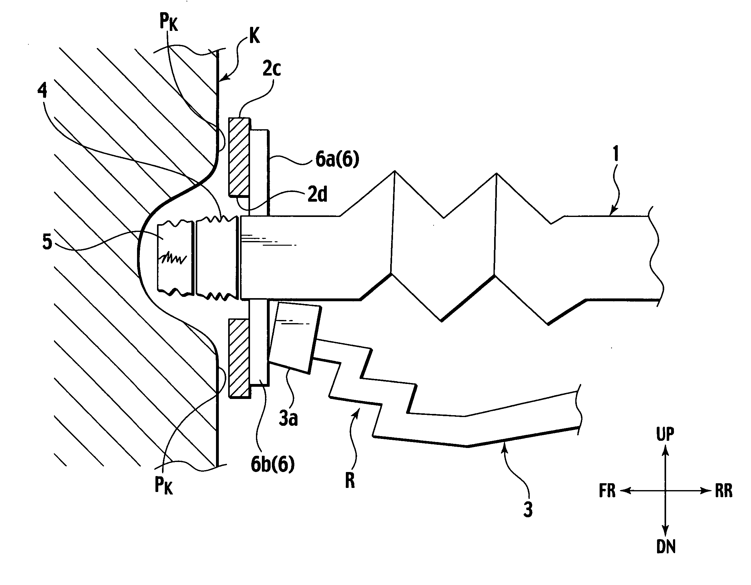
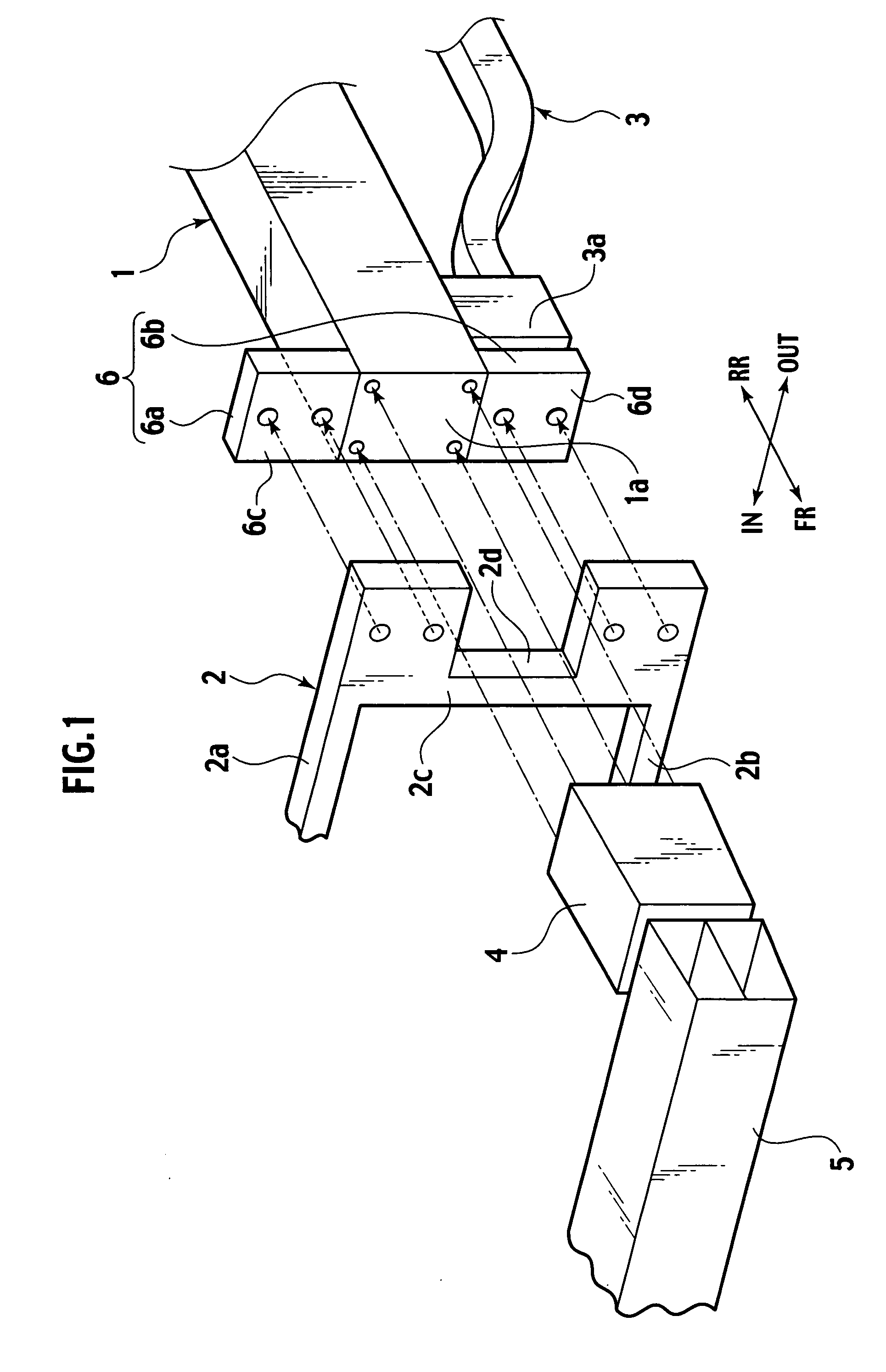
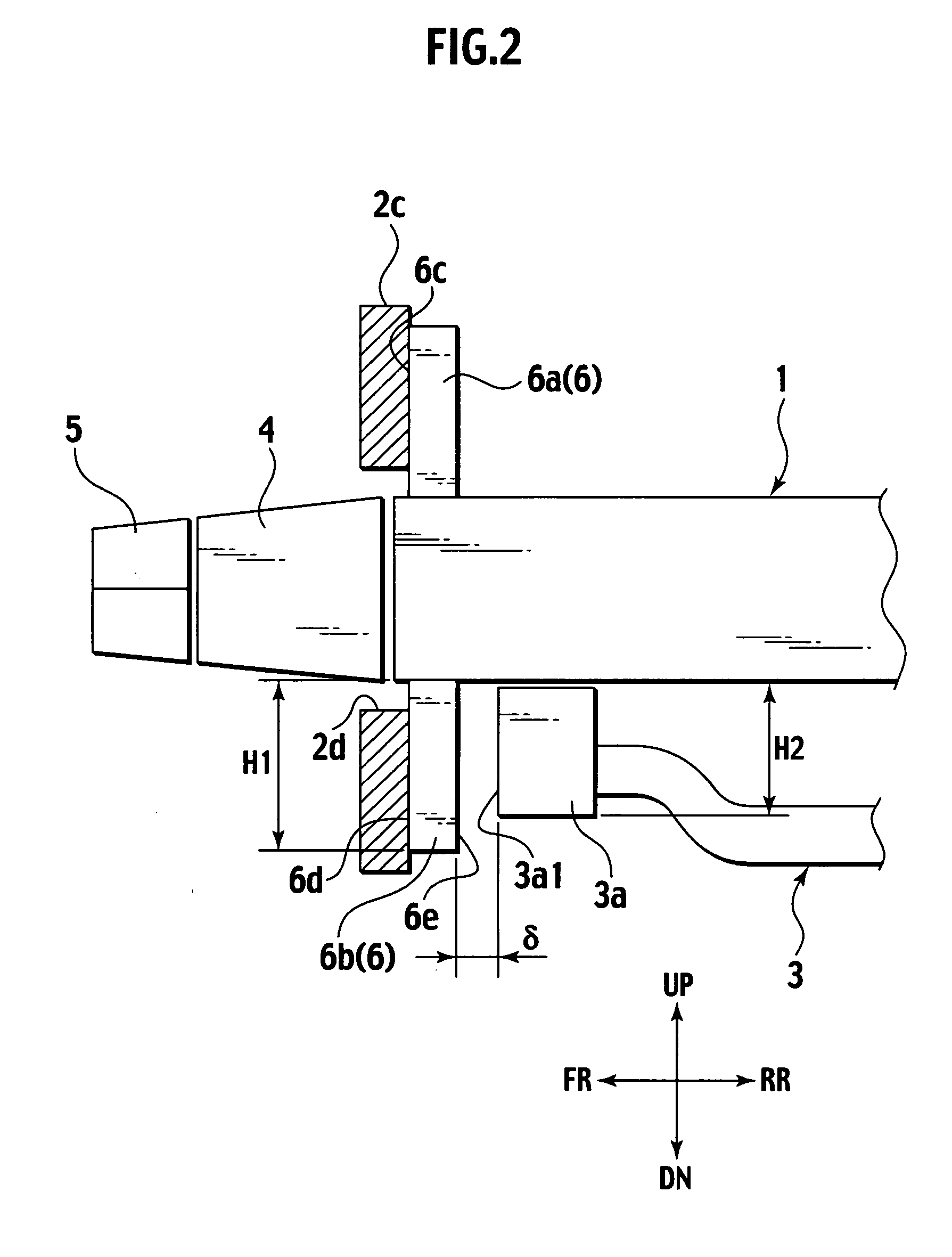
[0018] A vehicle front body structure of the embodiment is provided with, as shown in FIGS. 1 and 2, a pair of right and left side members 1 (only left one is shown in this embodiment) extending in the vehicle longitudinal direction on both sides in the vehicle transverse direction in the vehicle front body as longitudinal structural members, a radiator core support 2 as a vehicle transverse directional member to be mounted across the front ends of the side members 1, and a suspension member 3 with the front mounting portions thereof mounted to the lower side faces of the side members 1 on the front ends thereof. A bumper armature 5 is connected to the front ends of the side members 1 with bumper stays 4 provided therebetween, respectively.
[0019] Each of the side members 1 is formed to have a closed sectional structure with a rectangular cross section, and is configured to absorb i...
PUM
 Abstract
Description
Claims
Application Information