
Deflection yoke and picture tube apparatus using the same

a technology of picture tube and deflection yoke, which is applied in the direction of cathode ray tube/electron beam tube, basic electric elements, electric discharge tube, etc., can solve the problems of increasing the cost of deflection yoke and design difficulties of projection television set manufacturers, and achieves stable deflection yoke and improve reliability

Inactive Publication Date: 2005-10-06
MATSUSHITA TOSHIBA PICTURE DISPLAY CO LTD
View PDF5 Cites 0 Cited by
  • Summary
  • Abstract
  • Description
  • Claims
  • Application Information

AI Technical Summary

Benefits of technology

[0008] An object of the present invention is to provide a deflection yoke that has thus wound horizontal deflection coils and that allows stable processes for attaching the vertical deflection coils and the cores to the insulating frame, and also a picture tube apparatus using the deflection yoke.
[0013] According to the present invention, even when an insulating frame is placed on a workbench, with its opening on the screen face side facing downward, the insulating frame will not become unstable. Therefore, processes for attaching the vertical deflection coils and the core to the insulating frame can be carried out stably. Moreover, even when the deflection yoke is disposed with its opening on the screen face side facing downward during transport of the deflection yoke, the deflection yoke will not topple and be damaged due to external vibration or the like. Therefore, the reliability of the deflection yoke can be improved.

Problems solved by technology

With an increasing demand for energy saving in recent years, projection television set manufacturers are facing design difficulties.
However, in the technique disclosed in JP 2003-123669A, the horizontal correction coils 7 and the vertical correction coils 8 are necessary in addition to the deflection yoke 2, and the number of manufacturing steps required for assembling these coils also increases, resulting in a problem of an increase in the cost of the deflection yoke 2.

Method used


Image

  • Deflection yoke and picture tube apparatus using the same
  • Deflection yoke and picture tube apparatus using the same
  • Deflection yoke and picture tube apparatus using the same

Examples


Embodiment Construction

[0024] Hereinafter, the present invention will be described more specifically by way of an embodiment.

[0025] First, a projection tube apparatus equipped with a deflection yoke according to this embodiment is described with reference to FIG. 4. FIG. 4 is a top view showing a projection tube apparatus equipped with a deflection yoke according to an embodiment of the present invention.

[0026] As shown in FIG. 4, a projection tube apparatus 19 includes: a valve (vacuum envelope) made up of a face panel 21 made of glass or the like and having a substantially rectangular display portion 20 on its inner surface, a funnel 22 and a cylindrical neck portion 23 also made of glass or the like and connected to the rear portion of the face panel 21; and an electron gun 26 that emits an electron beam 25 and is housed in the neck portion 23. Here, a substantially rectangular screen face 27 is formed on an external surface of the face panel 21 that is opposite to the display portion 20. Furthermore...


PUM


Abstract

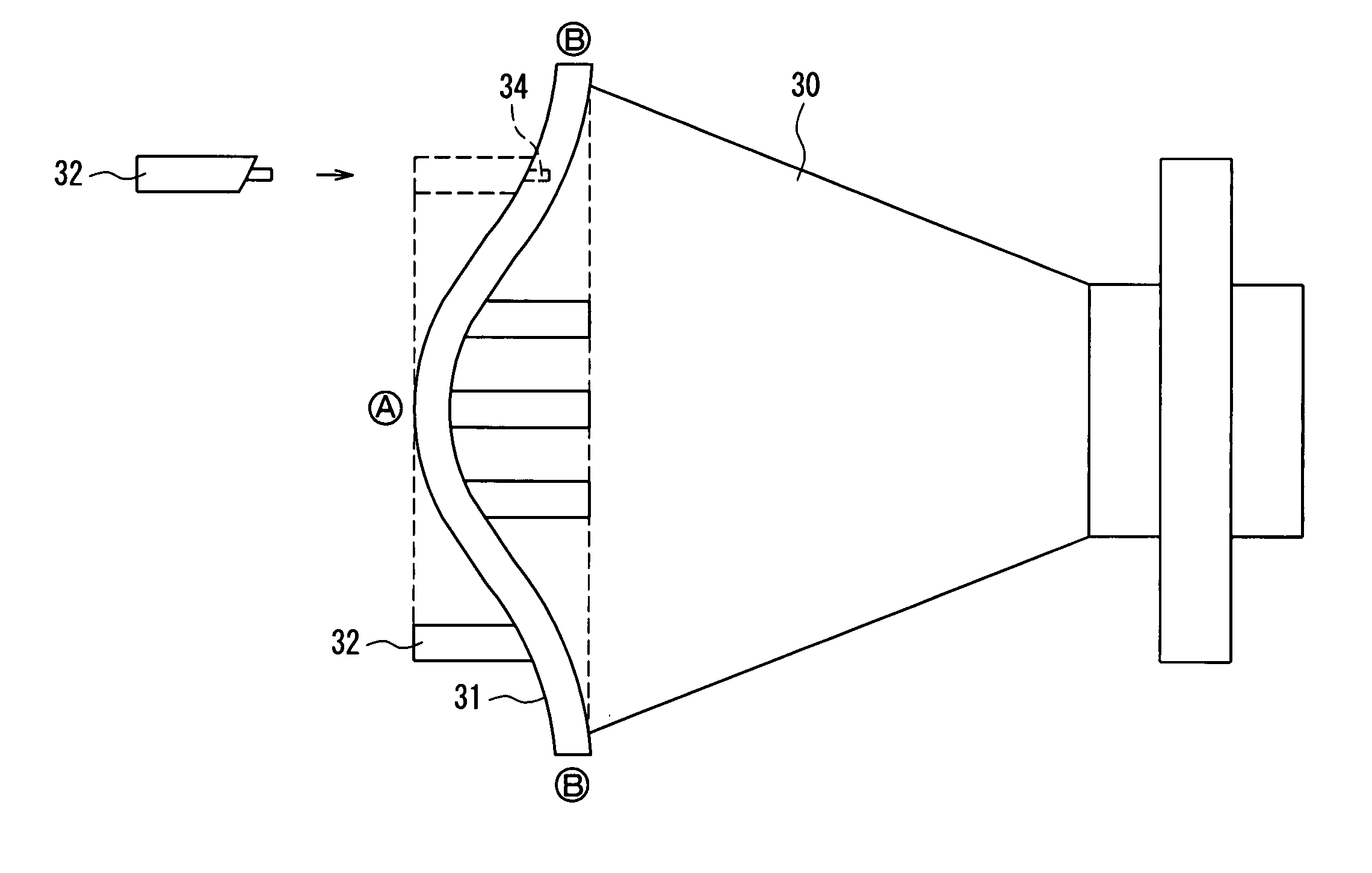
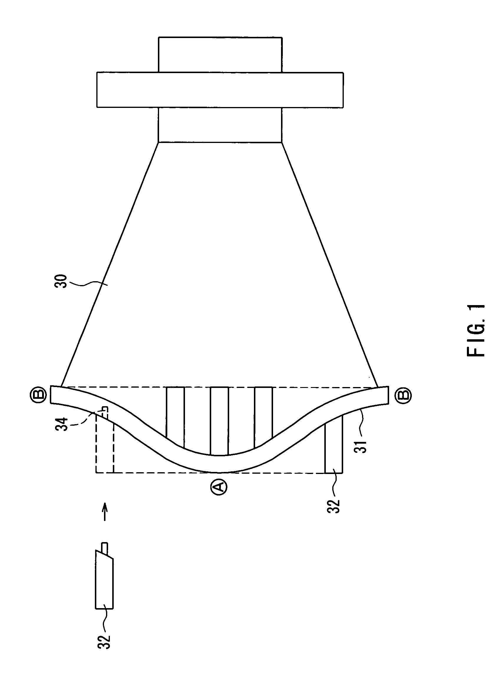
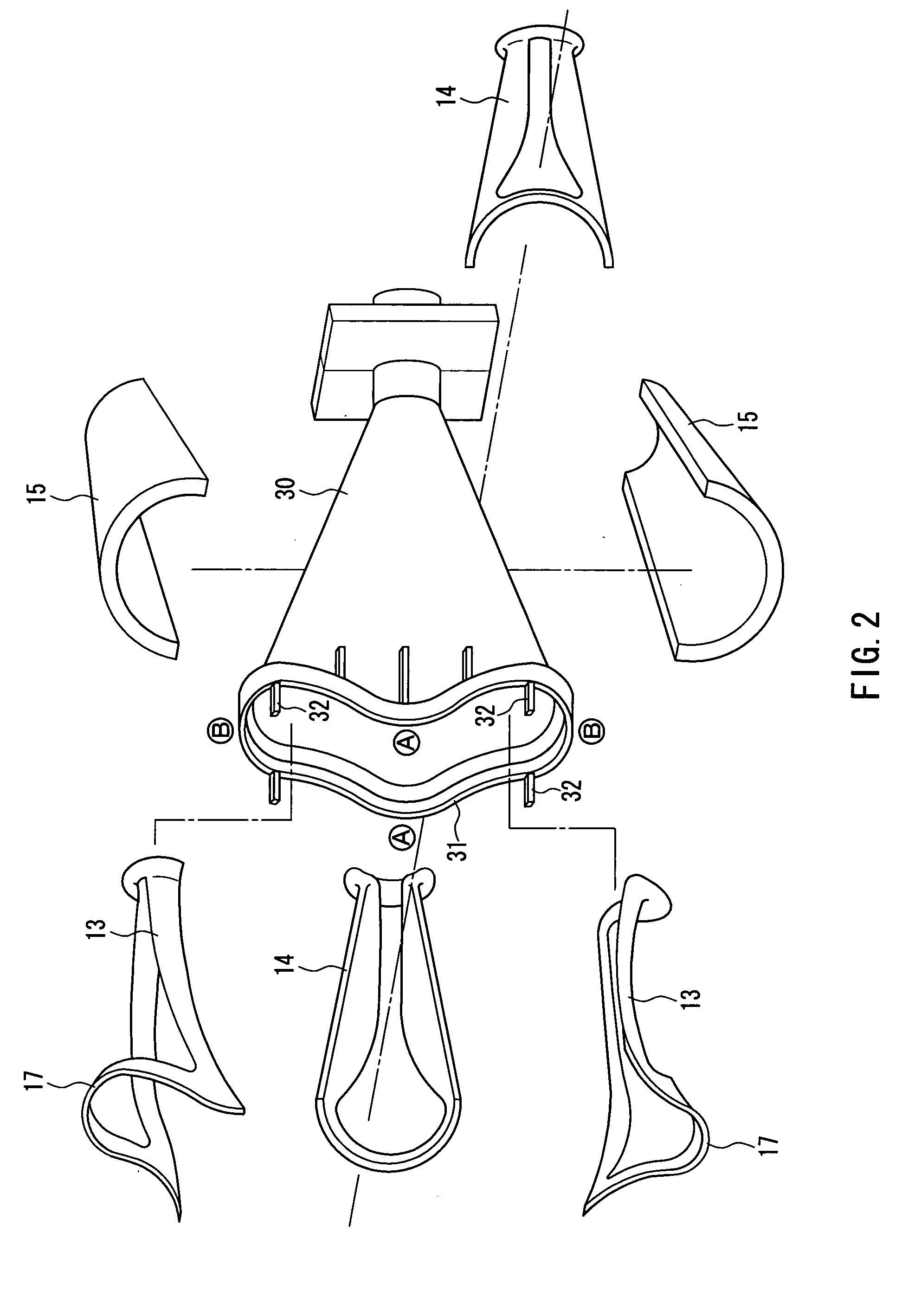
When a deflection yoke is provided by winding horizontal deflection coils so that right and left ends of its bend portion on a screen face side protrude farther toward the screen face side than the center of the bend portion does, works for attaching vertical deflection coils and a core to an insulating frame can be carried out stably. The insulating frame is resin-molded so that an opening on the screen face side is shaped along the bend portion on the screen face side of a pair of upper and lower horizontal deflection coils. Protrusions (convexes) are provided at four positions between right / left portion “A” in a X-axis (horizontal axis) direction and top / bottom portion “B” in a Y-axis (vertical axis) direction of a periphery of the opening on the screen face side of the insulating frame.

Description

FIELD OF THE INVENTION [0001] The present invention relates to a deflection yoke that is used for a picture tube apparatus such as a television set and a projection tube apparatus in order to deflect an electron beam emitted from an electron gun in horizontal and vertical directions. The present invention relates also to a picture tube apparatus using the deflection yoke. BACKGROUND OF THE INVENTION [0002] Generally, for higher resolution of projection-type projection televisions, a deflection field of a deflection yoke included in its projection tube apparatus is a substantially uniform field. Thus, pincushion distortions 1 (1a, 1b) of an image that occur due to geometric reasons as shown in FIG. 8 remain, and a correction circuit of a projection television set corrects these pincushion distortions 1. Particularly, it is known that the proportion of the power necessary to correct the pincushion distortion 1a in upper and lower portions of the screen accounts for at least 10% of the...

Claims


Application Information

Patent Timeline
Patent Type & Authority Applications(United States)
IPC IPC(8): H01J9/236H01J29/70H01J29/76
CPCH01J29/76H01J9/236
Inventor IWASAKI, KATSUYO
Owner MATSUSHITA TOSHIBA PICTURE DISPLAY CO LTD
Learn More