Information recording method and information recording/reproducing apparatus

a technology of information recording and recording equipment, which is applied in the field of information recording methods and information recording/reproducing equipment, can solve the problems of difficult adjustment of write pulses by the conventional method of measuring phase error between a readout signal and a clock signal, the s/n ratio of a readout signal will decrease, and the detection accuracy of a mark edge position will decrease, so as to reduce the density of recording equipment and increase the linear velocity , the effect of channel bit length

Inactive Publication Date: 2009-06-11
HITACHI LTD
View PDF3 Cites 1 Cited by
  • Summary
  • Abstract
  • Description
  • Claims
  • Application Information

AI Technical Summary

Benefits of technology

[0022]Here, the reason why the write-pulse parameter adjusted by carrying out trial writing using the varied channel bit length is applicable during user-data recording is described. The magnitude of thermal interference is characterized by the time interval from a heat application for forming a certain mark to a heat application for forming the next mark, and also by the heat conduction speed in the in-plane direction of a medium. Since the heat conduction speed of a medium is considered to be constant regardless of the linear velocity, the magnitudes of thermal interference are also considered to be almost equal if the write-clock frequency is constant. For this reason, the waveform parameter, which has been determined by carrying out trial writing under the condition that the recording density is reduced by fixing the write-clock frequency and by increasing the linear velocity, can be applied as an approximate parameter when recording at the original linear velocity. The same shall be applied also in cases where the channel bit length is reduced by reducing the write-clock frequency instead of increasing the linear velocity. Since the S / N ratio of the shortest mark signal / the shortest space signal is improved and the edge detection accuracy is improved thanks to the reduction in the recording density during test writing, the mark edge is easily controlled to an appropriate position.
[0023]According to the present invention, since the write pulse adjustment by mark edge detection is possible during test writing, drive units capable of handling high-capacity optical discs and capable of highly reliably recording / reproducing data can be manufactured at low cost.

Problems solved by technology

However, as the recording density increases and in turn the length of a mark or a space (channel bit length) per one bit of information is reduced, the S / N ratio of a readout signal will decrease due to lack of optical resolution of a light spot.
Then, the detection accuracy of a mark edge position will decrease, and therefore the write pulse adjustment by the conventional method of measuring the phase error between a readout signal and a clock signal becomes difficult.
In particular, if the channel bit length becomes small to such an extent that the light spot during reproduction cannot optically resolve a repetitive pattern of the shortest mark and the shortest space, then the readout-signal amplitude of this pattern becomes zero and the mark edge become completely undetectable.
In a practical sense, if the recording density exceeds approximately 27 GB / layer (a channel bit length of 69 nm), it is difficult to apply the conventional write pulse adjustment method of measuring the phase error between a readout signal and a clock signal.

Method used


Image

  • Information recording method and information recording/reproducing apparatus
  • Information recording method and information recording/reproducing apparatus
  • Information recording method and information recording/reproducing apparatus

Examples


Embodiment Construction

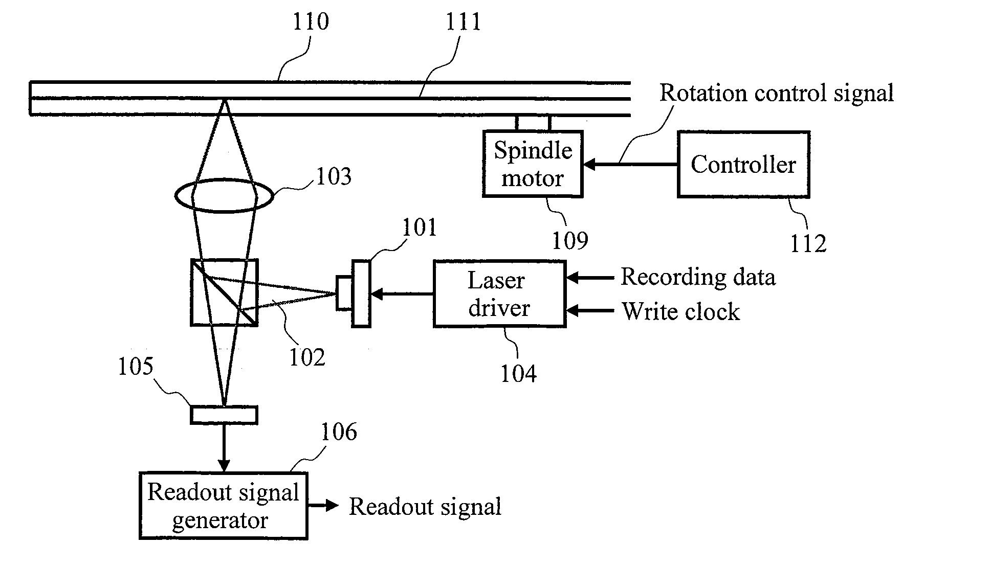
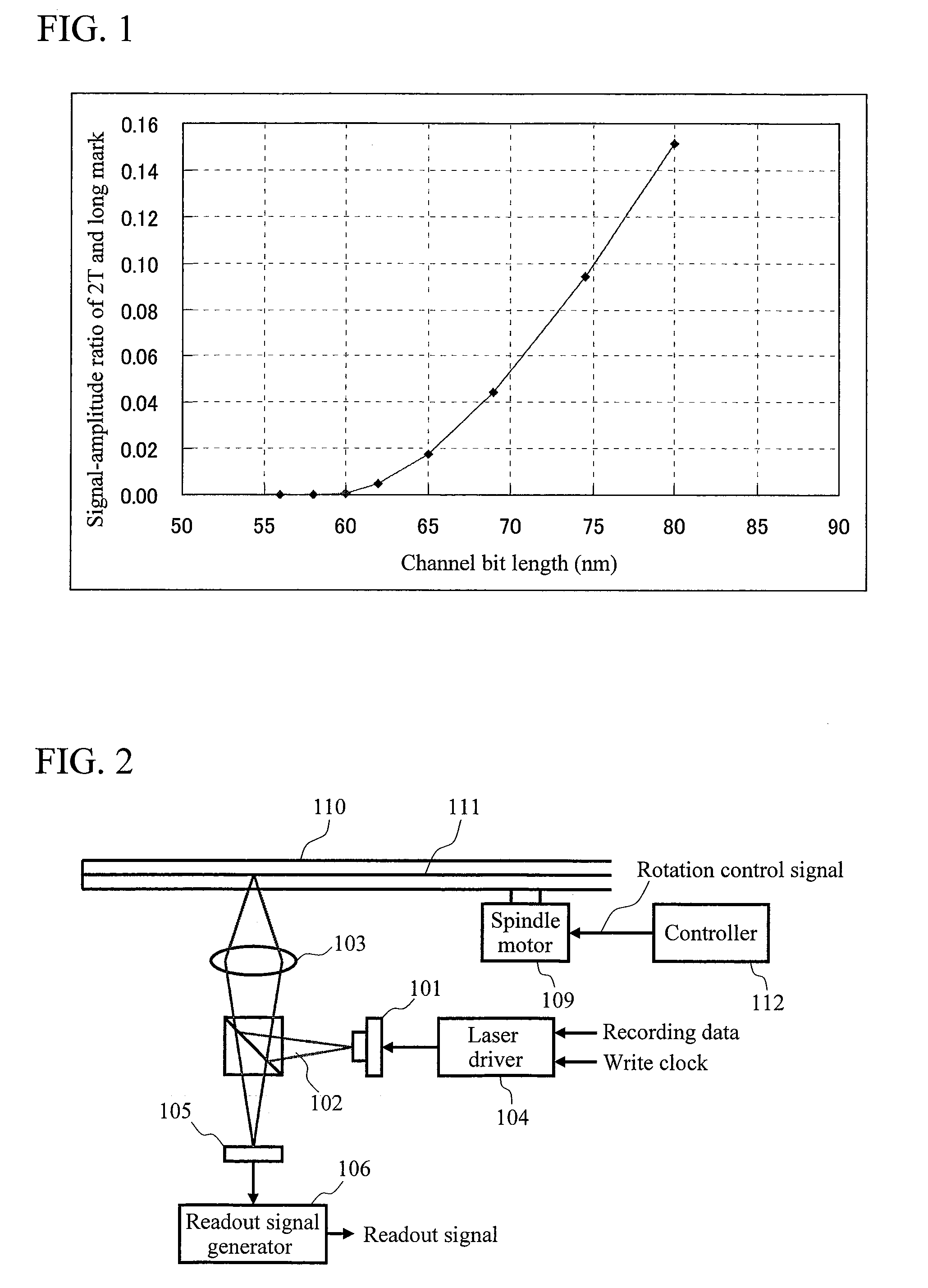
[0032]Hereinafter, embodiments of the present invention will be described with reference to the accompanying drawings. FIG. 2 is a diagram showing a basic configuration example of an information recording apparatus according to the present invention. Laser light 102 emitted from a laser diode 101 is focused onto an information recording layer 111 of an optical disc 110 by an objective lens 103. Recording or reproducing of information is carried out using the focused laser light. The laser light reflected by the information recording layer 111 is received by an optical detector 105. The optical detector outputs electric current proportional to the power of the received light. The output electric current is converted into a readout signal by a readout-signal generator 106. The optical disc 110 is fixed to a spindle motor 109 and is rotationally driven. The spindle motor 109 is driven by a pulse signal, and the rotational speed is controlled by the frequency of the pulse signal. A lase...


PUM

PropertyMeasurementUnit
wavelengthaaaaaaaaaa
lengthaaaaaaaaaa
channel bit lengthaaaaaaaaaa

Abstract

To make the adjustment of a write-pulse parameter on the basis of a phase error between a readout signal and a clock signal applicable also to high-density optical discs. The channel bit length during trial writing is made larger than that during user-data recording. Then, a write-pulse parameter adjusted by the trial writing is applied as it is or with a predetermined correction to user-data recording.

Description

CLAIM OF PRIORITY[0001]The present application claims priority from Japanese patent application JP 2007-317012 filed on Dec. 7, 2007, the content of which is hereby incorporated by reference into this application.BACKGROUND OF THE INVENTION[0002]1. Field of the Invention[0003]The present invention relates to information recording methods and information recording / reproducing apparatuses for recording information by forming a mark and a portion between marks by irradiating an information recording medium with a pulse-like modulated light.[0004]2. Description of the Related Art[0005]In a recording type optical disk, information is recorded by forming a mark and a portion between marks by focusing and irradiating a laser light onto an information recoding layer of a disc. A pulse-like modulated laser light is used in recording information. The power or the pulse width of a write pulse is adjusted in accordance with the recording characteristic of a medium by carrying out trial writing ...

Claims


Application Information

Patent Timeline
Patent Type & Authority Applications(United States)
IPC IPC(8): G11B7/0045
CPCG11B7/00458G11B20/10009G11B20/10055G11B2220/2541G11B20/10425G11B20/10481G11B20/10222
Inventor KUROKAWA, TAKAHIRO
Owner HITACHI LTD
Why Eureka
Try Eureka