Piezoelectric devices and methods and circuits for driving same

a technology of piezoelectric elements and circuits, applied in the direction of device details, positive displacement liquid engines, piezoelectric/electrostrictive device details, etc., can solve the problems of limited el lamp driver, causing audible noise, and affecting the use of el lamp driver circuits

Inactive Publication Date: 2005-10-06
PAR TECH
View PDF52 Cites 101 Cited by
  • Summary
  • Abstract
  • Description
  • Claims
  • Application Information

AI Technical Summary

Problems solved by technology

Despite its overall ingenious and overall beneficial utilization in piezoelectric pumps, some aspects of using a EL lamp driver circuit are problematic.
As a first example problem, the EL lamp driver is limited in that it operates only at a fixed frequency once installed.
As a second example problem, the output wave form of the EL lamp driver circuit is a modified sawtooth which creates audible noise in the piezo even under load (due to the sharp peak on the waveform output by the EL lamp driver circuit).
So when a drive waveform is applied that has frequency content outside of the targeted fundamental drive frequency, that extraneous frequency content adds little to the work output of the piezoelectric element but greatly increase

Method used


Image

  • Piezoelectric devices and methods and circuits for driving same
  • Piezoelectric devices and methods and circuits for driving same
  • Piezoelectric devices and methods and circuits for driving same

Examples


Embodiment Construction

of Drive Circuits

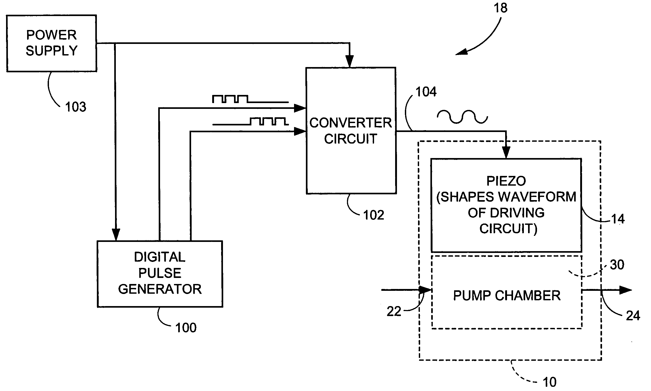
[0059] General non-limiting examples of the piezoelectric actuator drive circuit 18 are illustrated in FIG. 3 and FIG. 3A, FIG. 3B, FIG. 3C, FIG. 3D, FIG. 3E(1), FIG. 3E(2), FIG. 3F, FIG. 3G, FIG. 3H(1), FIG. 3H(2), FIG. 3I(1), FIG. 3I(2), FIG. 3I(3), and FIG. 3J. In each of the example embodiments and modes the piezoelectric actuator drive circuit 18 applies a series of low power, long period digital pulses to the converter circuit 102, so that converter circuit 102 can apply packet charges which are integrated by the piezoelectric actuator 14. In each of these embodiment, the piezoelectric actuator drive circuit 18 applies a drive signal to the piezoelectric actuator 14, with the piezoelectric actuator 14 comprising or being adjacent or proximate to a utilization device. The particular utilization device which uses or incorporates the piezoelectric actuator 14 depends upon the application and / or environment. One example, non-limiting utilization device discussed h...


PUM


Abstract

A drive circuit (18) senses a parameter of a piezoelectric actuator (14) operating in a device (10) and adjusts a drive signal of the piezoelectric actuator in accordance with the parameter. The drive circuit comprises a controller (100) which controls a drive signal applied to the piezoelectric actuator (14); a feedback monitor (122) which obtains a feedback signal from the piezoelectric actuator while the piezoelectric actuator works; and, a processor (116) which uses the feedback signal to determine the parameter of the piezoelectric actuator. In one example mode, the parameter of the piezoelectric actuator which is determined by the piezoelectric actuator drive circuit is the capacitance or dielectric constant of the piezoelectric actuator. In other example modes, the parameter of the piezoelectric actuator which is determined by the piezoelectric actuator drive circuit is impedance or resonant frequency of the piezoelectric actuator.

Description

[0001] This application is related to the following simultaneously-filed United States patent applications: U.S. patent application Ser. No. 10 / ______ (attorney docket: 4209-26) entitled “Piezoelectric Devices And Methods And Circuits For Driving Same”; U.S. patent application Ser. No. 10 / ______ (attorney docket: 4209-41) entitled “Piezoelectric Devices And Methods And Circuits For Driving Same”; and, U.S. patent application Ser. No. 10 / ______, (attorney docket: 4209-46) entitled “Piezoelectric Devices And Methods And Circuits For Driving Same”; all of which are incorporated by reference herein in their entirety.BACKGROUND [0002] 1. Field of the Invention [0003] This invention pertains to piezoelectric elements, and particularly to circuits and methods for driving piezoelectric elements utilized in such devices such as pumps, for example. [0004] 2. Related Art and Other Considerations [0005] A piezoelectric element is a crystalline material which produces an electric voltage when su...

Claims


Application Information

Patent Timeline
IPC IPC(8): B41J29/393F04B43/04H01L41/04
CPCF04B43/046H01L41/042A61M2205/0294A61M5/16831A61M5/16877A61M5/142H10N30/802
Inventor VOGELEY, JAMES
Owner PAR TECH
Why Eureka
Try Eureka