

Golf club head
a golf club and club head technology, applied in the field of golf club heads, can solve the problems of poor stability (accuracy) of the direction of the ball hit, inferior related techniques, and easy damage to the clubface, and achieve the effect of improving the directional stability of the ball hi
- Summary
- Abstract
- Description
- Claims
- Application Information
AI Technical Summary
Benefits of technology
Problems solved by technology
Method used
Image


Examples
first embodiment
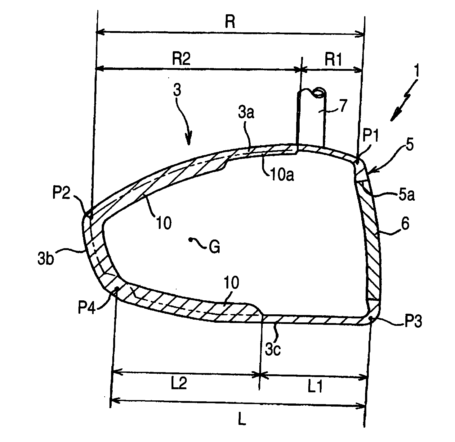
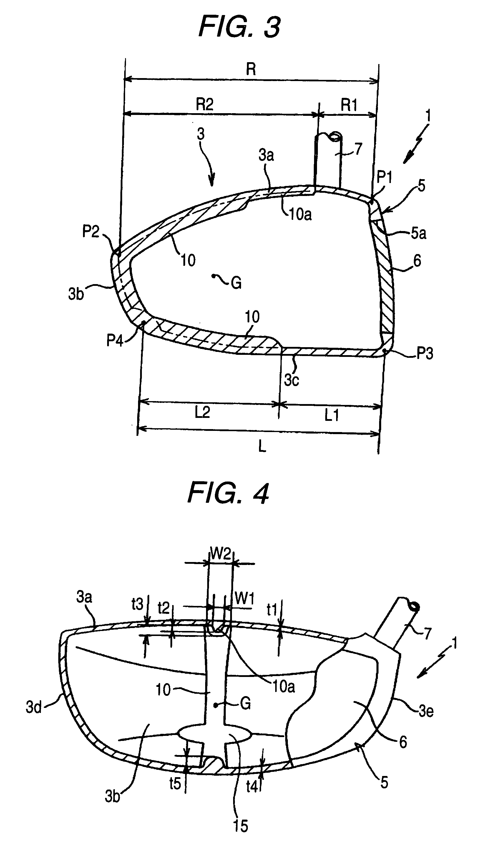
[0078] FIGS. 3 to 6 show a golf club head according to a first embodiment of the invention, in which FIG. 3 is a longitudinal sectional view taken along a line passing through a position where the center of gravity of a head exists, FIG. 4 is a transverse sectional view taken on a face side of the head, FIG. 5 is a plan view of the head, and FIG. 6 is a bottom view of the head.
[0079] A head body 1 of a golf club head (hereinafter, referred to as a head) according to the first embodiment includes a rear member 3 which is made up, in turn, of a crown portion 3a, a back portion 3b, a sole portion 3c, a toe portion 3d and a heal portion 3e, and a front member (a face portion) 5 which is welded to or integrated into the rear member 3. Then, an opening 5a is formed in the face portion 5, and a face member 6 is securely held in the opening via welding, press fitting or bonding, whereby the head body 1 is constructed into a hollow shell structure.
[0080] Note that all of the shell members ...
second embodiment
[0094]FIGS. 8 and 9 are such as to illustrate a second embodiment of the invention, in which FIG. 8 is a longitudinal sectional view of a golf club head taken along the line which passes through the center of gravity of the head and FIG. 9 is a plan view of the head.
[0095] In the embodiment that has been described before, while the weight-massed portion 10 is formed in such a manner as to extend continuously from the crown portion 3a to the sole portion 3c of the head body 1, a weight-massed portion 30, which extends in the face-to-back direction as shown in the drawings, may be formed only on a crown portion 3a. Namely, in heads of a hollow construction, in general, the sole portion tends to be made relatively heavy with a view to realizing a low center of gravity, and the crown portion tends to be formed relatively thin due to no adjustment being made for the center of gravity. Due to this, by forming the weight-massed portion 30 on the crown portion which constitutes the thin po...
third embodiment
[0096]FIGS. 10 and 11 are such as to illustrate a third embodiment of the invention, in which FIG. 10 is a plan view of a golf club head and FIG. 11 is a bottom view of the head.
[0097] While in the embodiments that have been described before, the weight-massed portions are formed in the direction normal to the face portion of the head, a weight-massed portion 40 according to this embodiment is formed in such a manner as to curve along the swing plane when a head body 1 is seen from the top. Namely, by forming the weight-massed portion 40 in such a manner as to so curve, the effect to make the shaft rotation follow the direction of the swing plane can be increased further, whereby the swing is made difficult to deflect and stable. In particular, an effect to make the turn of the head follow the direction of the swing plane is increased to thereby facilitate the shot of a draw ball (a ball path which slightly curves from the right to the left). As this occurs, in the event that a wei...
PUM
 Abstract
Description
Claims
Application Information