Continuously variable belt drive transmission

Inactive Publication Date: 2005-10-06
JATCO LTD
View PDF7 Cites 37 Cited by
  • Summary
  • Abstract
  • Description
  • Claims
  • Application Information

AI Technical Summary

Benefits of technology

[0004] An object of the present invention is to provide a continuously variable belt drive transmission capable of improving a friction coefficient of the mutually contacting surfaces of the belt and the pulleys to thereby enhance fuel economy. A further object of the present invention is to provide a continuously variable belt drive transmission capable

Problems solved by technology

However, a sufficient friction coefficient is not ensured even when the recesses and projections are formed merely on the side face of the metal element of the belt as described in the conventional art.
Basically, in the continuously variable belt drive transmissions, if slide occurs between contact portions of the tapered surface of the input or output pulley

Method used


Image

  • Continuously variable belt drive transmission
  • Continuously variable belt drive transmission
  • Continuously variable belt drive transmission

Examples


Example

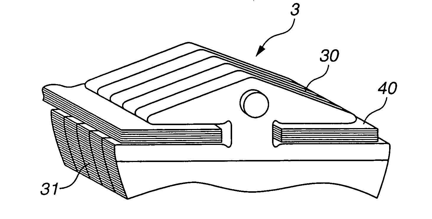
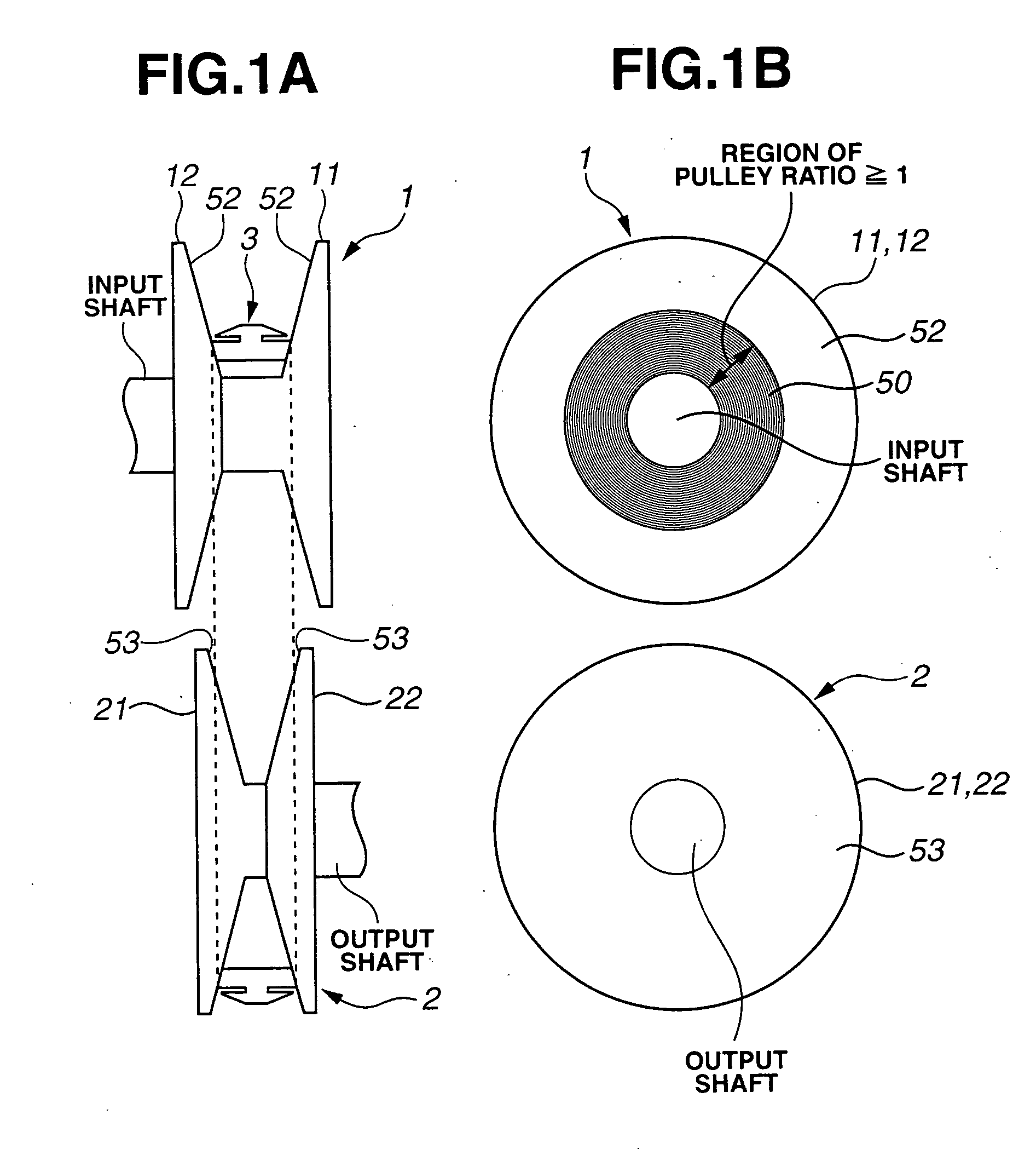
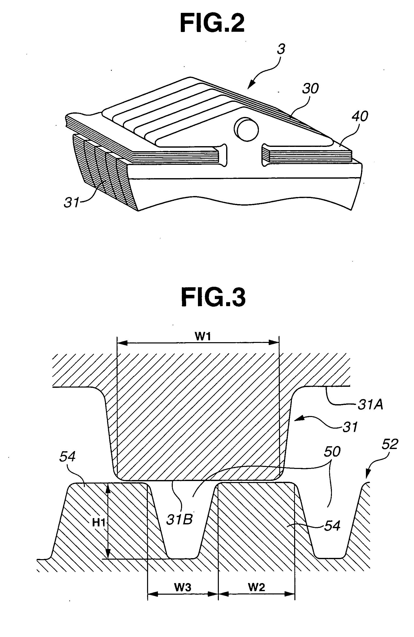
[0024] In the followings, embodiments of the present invention will be described with reference to the accompanying drawings. FIG. 1A schematically illustrates a relative arrangement of primary pulley 1, secondary pulley 2 and endless belt 3 of a continuously variable belt drive transmission (hereinafter referred to as a belt drive CVT). FIG. 1B illustrates primary pulley 1 on an input shaft and secondary pulley 2 on an output shaft as viewed in an axial direction of the input and output shafts. As illustrated in FIG. 1A, primary pulley 1 as an input pulley is constructed of stationary pulley half 11 formed integrally with the input shaft, and moveable pulley half 12 moveable in an axial direction of the input shaft. Similarly, secondary pulley 2 as an output pulley is constructed of stationary pulley half 21 formed integrally with the output shaft, and moveable pulley half 22 moveable in an axial direction of the output shaft. Endless belt 3 is fitted between primary and secondary ...


PUM


Abstract

A continuously variable belt drive transmission, including input and output pulleys each having axially opposed tapered surfaces, and an endless belt including a plurality of metal elements each having opposed side faces contacted with the respective tapered surfaces of the input and output pulleys. Each of the opposed side faces is formed with a plurality of microscopic projections and recesses arranged along a radial direction of the input and output pulleys upon being in contact with the respective tapered surfaces of the input and output pulleys. The tapered surfaces of at least the input pulley are formed with microgrooves that are radially spaced from one another and have a pitch not more than a width of each of the microscopic projections on the side faces of the metal element.

Description

BACKGROUND OF THE INVENTION [0001] The present invention relates to a continuously variable belt drive transmission, and more particularly to a microstructure on a surface of a pulley which is contacted with a belt. [0002] Japanese Patent No. 3209323 describes a metal element of an endless belt for continuously variable belt drive transmissions. The metal element has a side face adapted to be contacted with tapered surfaces of input and output pulleys, on which microscopic recesses and projections are formed in order to increase friction coefficients of the side face of the metal element and the tapered surfaces of the input and output pulleys. SUMMARY OF THE INVENTION [0003] However, a sufficient friction coefficient is not ensured even when the recesses and projections are formed merely on the side face of the metal element of the belt as described in the conventional art. Basically, in the continuously variable belt drive transmissions, if slide occurs between contact portions of...

Claims


Application Information

Patent Timeline
IPC IPC(8): F16H55/38F16G1/00F16G1/21F16G5/16F16H9/12F16H9/24F16H55/49F16H55/56
CPCF16G5/16F16G5/163F16H55/38F16H55/56E03B9/10G01F15/14
Inventor YOSHIDA, MAKOTOKATOU, YOSHIAKIITO, YASUOKINO, NOBUO
Owner JATCO LTD
Why Eureka
Try Eureka