Drive mechanism for a four wheel drive transverse engine-mounted vehicle

a technology of transverse engine and drive mechanism, which is applied in fluid gearings, transportation and packaging, gearing, etc., can solve the problems of increasing and achieve the effect of suppressing the increase of the weight of the differential uni

Inactive Publication Date: 2005-10-06
JATCO LTD
View PDF9 Cites 3 Cited by
  • Summary
  • Abstract
  • Description
  • Claims
  • Application Information

AI Technical Summary

Benefits of technology

[0006] An object of this invention is to suppress increases in weight of ...

Problems solved by technology

A new problem thus arises where the ...

Method used


Image

  • Drive mechanism for a four wheel drive transverse engine-mounted vehicle
  • Drive mechanism for a four wheel drive transverse engine-mounted vehicle
  • Drive mechanism for a four wheel drive transverse engine-mounted vehicle

Examples


Embodiment Construction

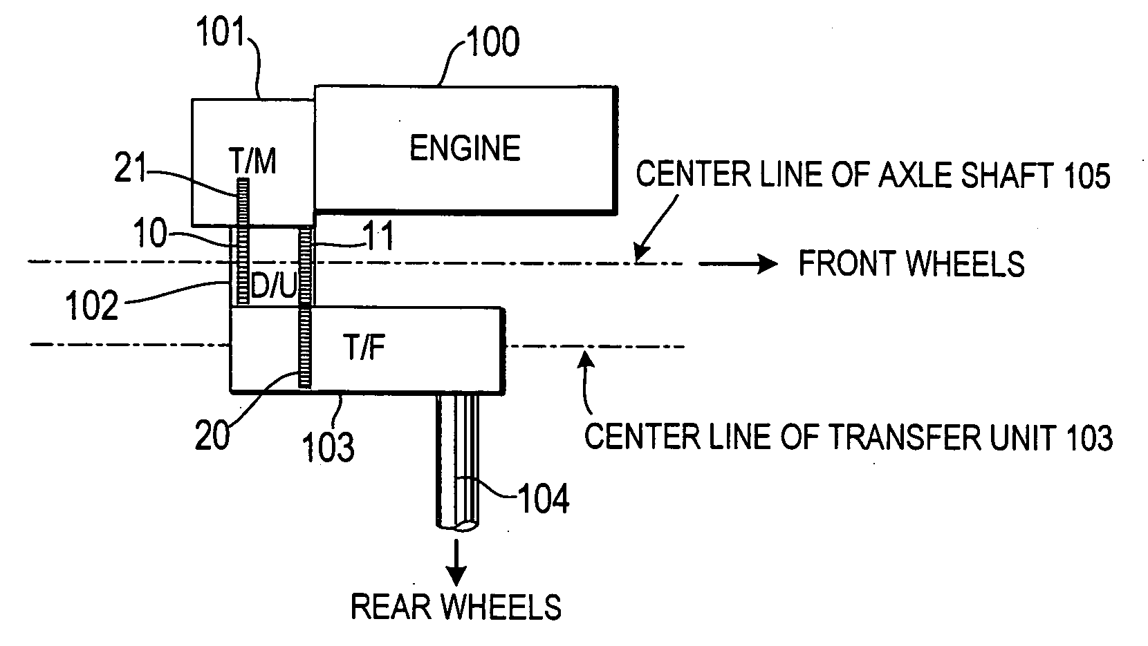
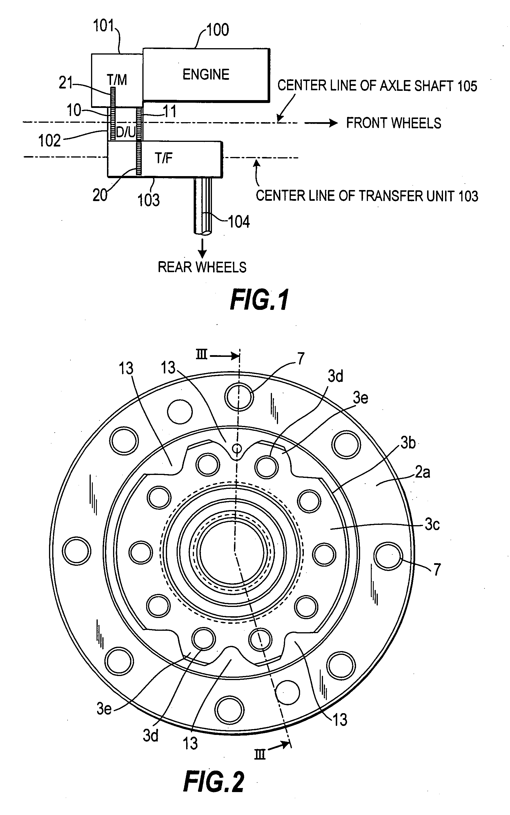
[0015]FIG. 1 shows a schematic diagram of a drive mechanism of a four wheel drive vehicle of this invention.

[0016] An engine 100 is a so-called transverse-mounted engine having a crankshaft of the engine 100 disposed in a right and left direction of a vehicle. A transmission 101 is disposed onto a left side of the engine 100. A differential unit 102 is connected to a vehicle rear side of the transmission 101. A transfer unit 103 is disposed rearward of the differential unit 102.

[0017] Drive force from the engine 100 is transmitted from the transmission 101 and the differential unit 102 to an axle shaft 105, driving front wheels, and is transmitted from the differential unit 102 and the transfer unit 103 to a propeller unit 104, driving rear wheels. This layout is one in which the central axis of the transfer unit 103 is disposed in parallel with, and is offset rearward of, the central axis of the axle shaft 105 that drives the front wheels. Consequently, a space can be secured dir...


PUM


Abstract

A differential unit (102) is provided with a ring gear (10) that meshes with an output gear (21) of a transmission (101), an axle shaft (105) that is connected to front wheels, and a drive gear (11) that is fixed by screws to a plurality of boss portions (3e) and spaced apart from the ring gear (10). A transfer unit (103) disposed rearward of the differential unit (102) is provided with a driven gear (20) that meshes with the drive gear (11). Drive force is transmitted from the driven gear (20) to a propeller shaft (104), and the propeller shaft (104) transmits the drive force to rear wheels. First material-removed portions (12) made of concave portions are formed in an inner circumference of a portion of a case (1) to which the axle shaft (105) is mounted. Second material-removed portions (13) made of concave portions that extend in an axial direction of the axle shaft (105) are formed between the plurality of boss portions (3e).

Description

FIELD OF THE INVENTION [0001] This invention relates to a drive mechanism for a four wheel drive transverse engine-mounted vehicle. BACKGROUND OF THE INVENTION [0002] JP9-150641A, published by the Japan Patent Office in 1997, discloses a drive mechanism of a four wheel drive transverse engine-mounted vehicle shown in FIG. 4. In this mechanism, an axle shaft (not shown) connected to a differential unit 202 is disposed coaxially with an output shaft (not shown) connected to a propeller shaft 204 of a transfer unit 203. [0003] Rotation of the engine is transferred from the differential unit 202 to front wheels through the axle shaft, and is also transmitted to the output shaft of the transfer unit 203. A bevel gear changes the transmission direction of the transmitted rotation of the output shaft and transmits the rotation to the propeller shaft 204. The propeller shaft 204 drives rear wheels through a rear differential unit (not shown). SUMMARY OF THE INVENTION [0004] In the conventio...

Claims


Application Information

Patent Timeline
IPC IPC(8): F16H37/08F16H47/04B60K17/344F16H48/08F16H48/38F16H48/40F16H57/037F16H57/038F16H57/039
CPCB60K17/344F16H48/08F16H48/40F16H2048/385Y10T74/2186
Inventor SHIRATO, KOUICHIROUKIM, HANJUNHAGIHARA, TAKANORI
Owner JATCO LTD
Why Eureka
Try Eureka