Multiplier sign extension method and architecture

a multiplication sign and extension method technology, applied in the field of multiplication sign extension method and architecture, can solve the problems of wasting judgment and operation time, affecting performance, etc., and achieve the effect of reducing the waste of chip area and reducing the size of the multiplier

Inactive Publication Date: 2005-10-06
ALICORP
View PDF4 Cites 4 Cited by
  • Summary
  • Abstract
  • Description
  • Claims
  • Application Information

AI Technical Summary

Benefits of technology

[0014] One object of the present invention is to provide a multiplier sign extension method and architecture for encoding operations used by a multiplier of a DSP, in which a plurality of complementary bits is provided for encoding of sign extension without increasing critical paths to reduce waste of chip area and make the multiplier smaller.
[0015] To achieve the above object, the method comprises the steps of: determining the width of the multiplier to obtain a sign extension bit total value; encoding a multiplier by means o

Problems solved by technology

A layer of correction row, however, is added to increase critical paths, hence affecting the performance.
Zero-extension or one-extension may be perfo

Method used


Image

  • Multiplier sign extension method and architecture
  • Multiplier sign extension method and architecture
  • Multiplier sign extension method and architecture

Examples


case 1

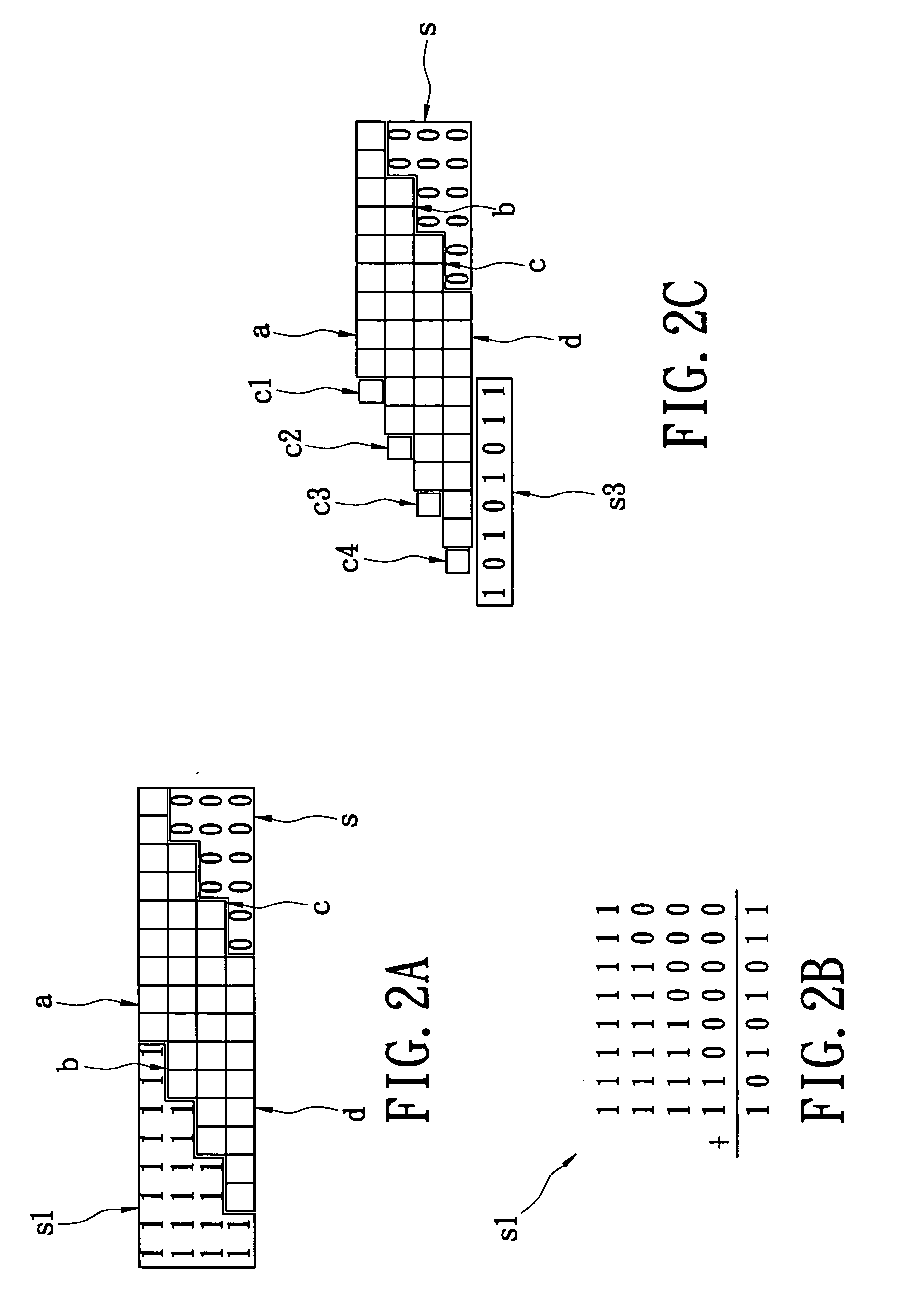
[0026] As shown in FIG. 2C, a first complementary bit c1 is provided before the MSB of the first partial product term a, a second complementary bit c2 is provided before the MSB of the second partial product term b, a third complementary bit c3 is provided before the MSB of the third partial product term c, and a fourth complementary bit c4 is provided before the MSB of the fourth partial product term d. The lowermost row is the total value s2 of sign extension bits obtained in advance. If the MSB of the above partial product term a, b, c, or d is 1 (i.e., the partial product term is negative), the sign extension bit region s1 is correctly set to 1. The corresponding complementary bit is thus set to 0 without affecting the correct value. If the MSB is 0 (i.e., the partial product term is positive), the sign extension bit region s1 is wrongly set to 1. The complementary bit is thus set to 1. In binary addition, a binary number with all bits being “1” added to by 1 sets all bits to 0 ...

case 2

[0033] if the MSB is 0, c5, c6 and c1 are set to 100.

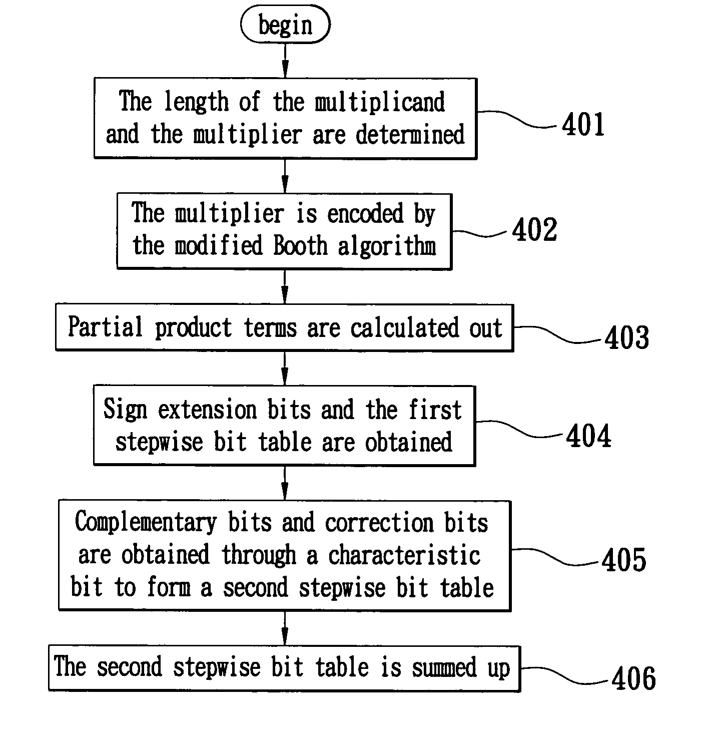
[0034] Reference is made to FIG. 4. First, the width of a multiplier is determined. That is, the numbers of bits of the multiplicand and multiplier are known, and the sign extension bit total value (a constant value obtained by summing up the sign extension bit region) is also determined (Step 401). Next, the multiplier is encoded by the modified Booth algorithm to obtain possible values (−M, +M, −2M, +2M) of partial product terms through 2's complement and shifting. The multiplier is taken apart with 3 bits as the unit. If there is one group having less than three bits after the multiplier is taken apart, “0” or “1” must be filled in without affecting the result (Step 402). The multiplicand is then multiplied by the above encoded multiplier to obtain partial product terms (Step 403). The partial product terms are arranged according to the rules of the modified Booth algorithm to obtain sign extension bits and a first stepwise bi...


PUM


Abstract

A multiplier sign extension method and architecture are used for encoding operations of a multiplier of a digital signal processor. The multiplier sign extension method comprises the steps of: determining the width of the multiplier to obtain a sign extension bit total value; encoding a multiplier by means of the modified Booth algorithm; calculating out a plurality of layers of partial product terms by multiplying a multiplicand by the encoded multiplier to form a first stepwise bit table; setting a plurality of complementary bits, a first correction bit and a second correction bit to form a second stepwise bit table; and summing up the plurality of layers of the second stepwise bit table. Without increasing critical paths, a plurality of complementary bits is provided for encoding of sign extension to reduce waste of chip area and make the multiplier smaller.

Description

BACKGROUND OF THE INVENTION [0001] 1. Field of the Invention [0002] The present invention relates to a multiplier sign extension method and architecture, whereby a plurality of complementary bits is provided for encoding a multiplier to reduce waste of chip area and make the multiplier smaller. [0003] 2. Description of the Related Art [0004] Multipliers are one kind of basic operation component used for almost complex operations. They are also required for the most representative operation—multiplier accumulator (MAC) in digital signal processors (DSP). Multipliers are widely used for digital signal processing like digital filtering. Additionally, a plurality of MACs is accommodated in most existent microprocessors so that they can complete the operations of multiplication and addition within an instruction period. [0005] Generally speaking, a modified Booth algorithm is used for design of a multiplier. This algorithm is an encoding technique capable of reducing half (N / 2) of the nu...

Claims


Application Information

Patent Timeline
IPC IPC(8): G06F7/533G06F7/499G06F7/52
CPCG06F7/49994G06F7/5336
Inventor LO, YU-CHENG
Owner ALICORP
Why Eureka
Try Eureka