Storage system and back-up method for storage system

a storage system and backup technology, applied in the field of storage systems, can solve the problems of data generation management, data cannot serve the purpose of data back-up on its own, system load increases, etc., and achieve the effect of reducing the amount of storage capacity required for back up, and reducing the amount of data transferred

Active Publication Date: 2005-10-06
RAKUTEN GRP INC
View PDF7 Cites 35 Cited by
  • Summary
  • Abstract
  • Description
  • Claims
  • Application Information

AI Technical Summary

Benefits of technology

[0017] Moreover, the generational management information records the storage contents of the first volume in the form of differential data. Therefore, in contrast to a method in which the contents of the volume at any given point in time are copied completely and exactly, only the difference with respect to the previous generation needs to be managed, for example, and therefore the amount of storage capacity required for back up can be reduced, and the data transfer time can also be shortened.
[0018] In the present embodiment, t

Problems solved by technology

Consequently, if the back-up data is managed by means of a plurality of generations, then a large number of volumes are required and hence the back-up costs increase.
Moreover, each time a new-generation volume is created, then it is necessary to execute an initial copy for transferring the whole volume, and hence the system load increases.
However, the actual data used for managing generations on the basis of differential snapshots is not backed up, and there only exists one versio

Method used


Image

  • Storage system and back-up method for storage system
  • Storage system and back-up method for storage system
  • Storage system and back-up method for storage system

Examples


first embodiment

1. First Embodiment

[0047] Firstly, an example of a disk array device provided respectively in the primary site and the secondary site is described, whereupon the unique composition according to the present invention is described. The disk array device in the primary site and the disk array device in the secondary site may also have different compositions.

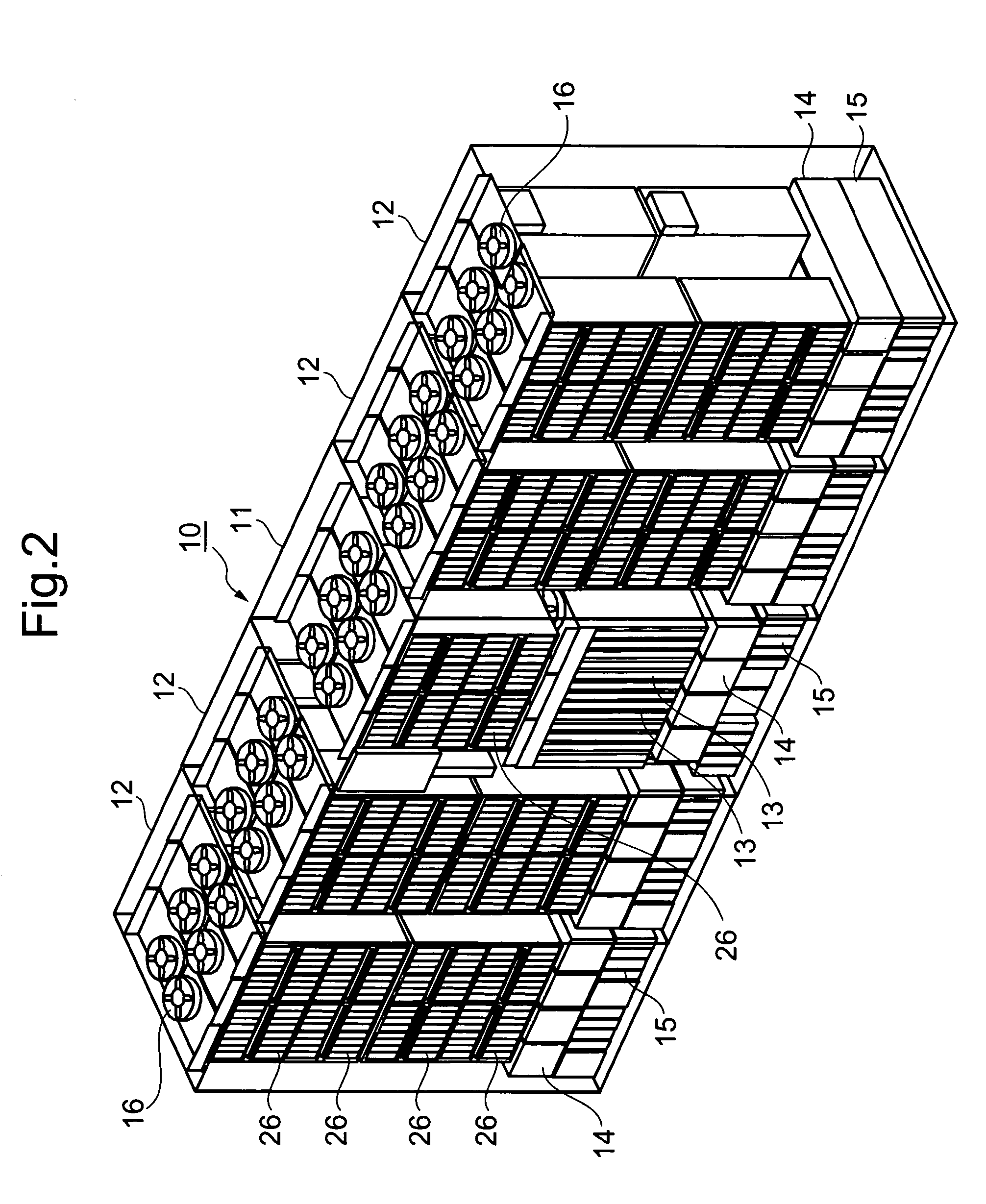
[0048]FIG. 2 is a general oblique view showing the external composition of a disk array device 10. The disk array device 10 may be constituted, for example, by a base frame body 11 and a plurality of add-on frame bodies 12.

[0049] The base frame body 11 is the smallest compositional unit of the disk array device 10, and it is provided with both storage functions and control functions. The add-on frame bodies 12 are optional items of the disk array device 10, and are controlled by means of the control functions provided in the base frame body 11. For example, it is possible to connect a maximum of four add-on frame bodies 12 to the ...

second embodiment

2. Second Embodiment

[0105] A second embodiment is now described on the basis of FIG. 9. The present embodiment is equivalent to a modification example of the first embodiment. The characteristic feature of the present embodiment lies in the fact that only the back-up data for a previously designated generation is transferred to the secondary site and held in same.

[0106]FIG. 9 is a flowchart showing an overview of back-up processing. Firstly, the disk array device 100 of the primary site acquires the generation to be backed up (S51). The generation for which data is to be backed up can be instructed to the disk array device 100 by the host 30.

[0107] The disk array device 100 transmits the respective storage contents of the main volume 110 and the main pool 120, to the disk array device 200 in the secondary site (S52, S53). Thereupon, the disk array device 100 respective acquires the data sizes of the differential bitmap table 151 and the withdrawal destination address management ta...

third embodiment

3. Third Embodiment

(Third Embodiment)

[0110] A third embodiment is now described on the basis of FIG. 10 and FIG. 11. The present embodiment is equivalent to a modification example of the first embodiment. The characteristic feature of the present embodiment lies in the fact that copies of a main volume, a main pool, and respective generational management information, held in the copy destination are transferred to the copy source, on the basis of an instruction from the user.

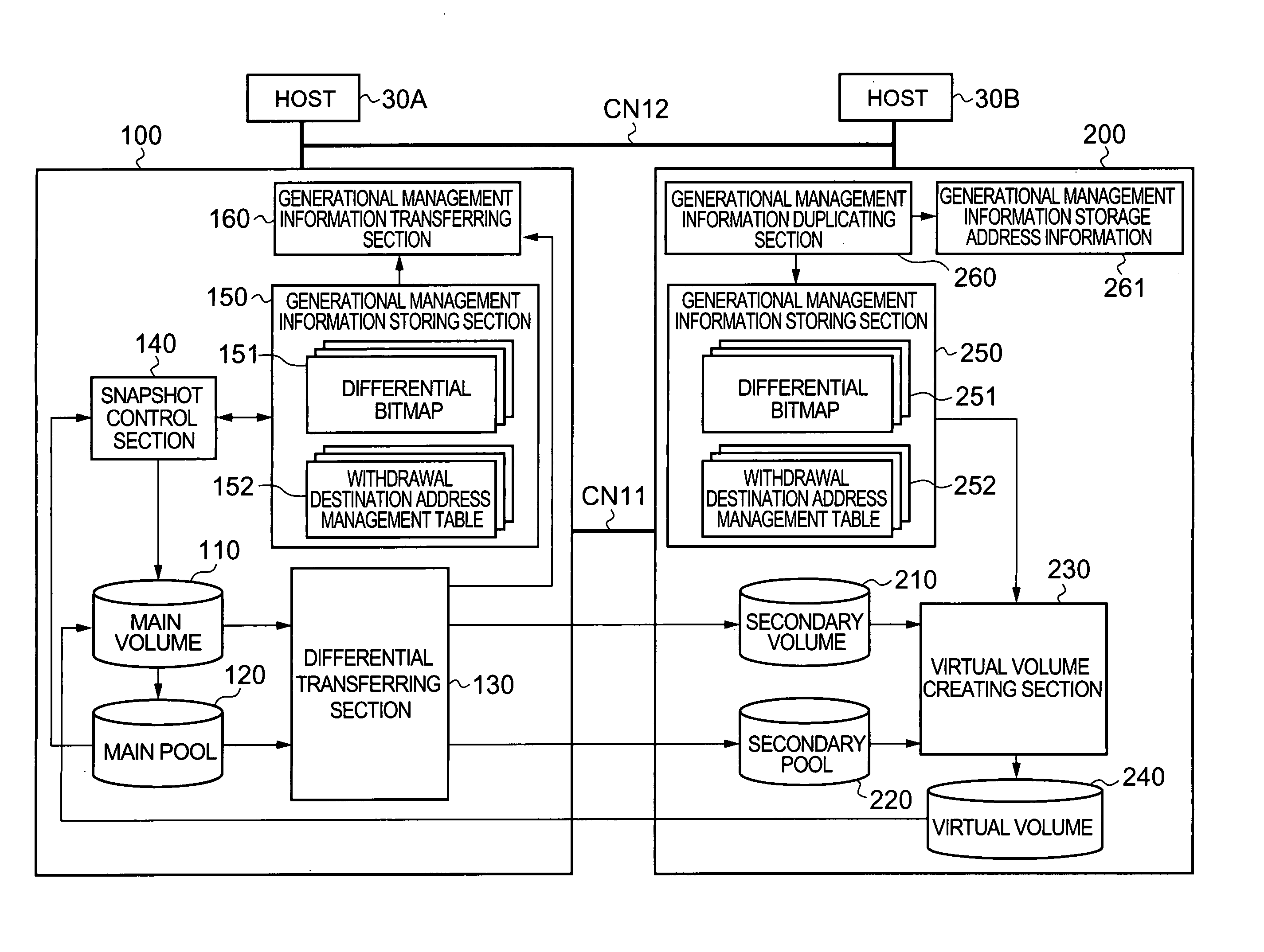
[0111]FIG. 10 is an approximate block diagram showing the general composition of a storage system. The disk array device 200 in the secondary site comprises a restoring section 270. In FIG. 10, in order to facilitate the description, the virtual volume creating section 230 is omitted from the drawing.

[0112] As shown in FIG. 11 as well, the restoring section 270 respectively transfers the storage contents of the secondary volume 210, the storage contents of the secondary pool 220, and the generational managem...


PUM


Abstract

The present invention provides a storage system whereby it is also possible to back up the generational management information of a copy source disk array device. The disk array device of the primary site manages back-up data of a main volume, in a plurality of generations, by means of differential snapshots. The differential data of the main volume and the main pool is transferred from the primary site to the secondary site, at a prescribed timing. The secondary site holds the secondary volume, which is a copy of the main volume, and a secondary pool which is a copy of the main pool. The primary site also transfers the generational management information to the secondary site. The generational management information may also comprise a differential bitmap table and a withdrawal destination address management table. The secondary site holds a copy of the generational management information. Thereby, it is possible to back up the whole of the data, including the generational management information, and hence protection against failure is improved.

Description

CROSS-REFERENCE TO RELATED APPLICATIONS [0001] This application relates to and claims priority from Japanese Patent Application No. 2004-102377 filed on Mar. 31, 2004, the entire disclosure of which is incorporated herein by reference. BACKGROUND OF THE INVENTION [0002] 1. Field of the Invention [0003] The present invention relates to a storage system capable of generational management, and a back-up method for a storage system. [0004] 2. Description of the Related Art [0005] For example, in various organizations, such as businesses, self-governing bodies, schools, or the like, large volumes of data of various different types are managed. These large volumes of data are managed by a storage system formed separately from a host computer. The storage system is constituted by comprising at least one or more storage device, such as a disk array device, for example. [0006] A disk array device is constituted by arranging storage devices, such as hard disk drives, or semiconductor memory d...

Claims


Application Information

Patent Timeline
IPC IPC(8): G06F3/06G06F12/16
CPCG06F11/1448G06F11/1451G06F11/1456G06F2201/84G06F11/201G06F11/2089Y10S707/99953Y10S707/99955
Inventor USHIJIMA, TAKUMAKUMAGAI, MASATOSATO, EIICHIKOMAKI, TOSHIO
Owner RAKUTEN GRP INC
Why Eureka
Try Eureka