
Washing machine

a washing machine and washing machine technology, applied in the field of washing machines, can solve the problems of waste of energy in the washing machine and high energy consumption in the heating air, and achieve the effect of preventing waste of cooling water and drying laundry faster

Inactive Publication Date: 2005-10-13
LG ELECTRONICS INC
View PDF5 Cites 19 Cited by
  • Summary
  • Abstract
  • Description
  • Claims
  • Application Information

AI Technical Summary

Benefits of technology

[0009] An object of the present invention is to provide a washing machine for circulating heated air within a cabinet, for drying laundry faster.
[0010] Another object of the present invention is to provide a washing machine, in which cooling water held on a bottom of a tub is circulated, for preventing waste of the cooling water.
[0016] Preferably, the circulating hose is extended to a position higher than a point where the circulating hose is connected to the water supply device, or the duct, and bent downward therefrom before the circulating hose is connected to the water supply device, or the duct, for preventing reverse flow of the cooling water.
[0020] Preferably, the circulating hose is extended to a position higher than a point where the circulating hose is connected to the water supply device, or the duct, and bent downward therefrom before the circulating hose is connected to the water supply device, or the duct, for preventing reverse flow of the cooling water.
[0029] Preferably, the circulating hose is extended to a position higher than a point where the circulating hose is connected to the water supply device, or the duct, and bent downward therefrom before the circulating hose is connected to the water supply device, or the duct, for preventing reverse flow of the cooling water.
[0037] Preferably, the circulating hose is extended to a position higher than a point where the circulating hose is connected to the water supply device, or the duct, and bent downward therefrom before the circulating hose is connected to the water supply device, or the duct, for preventing reverse flow of the cooling water.

Problems solved by technology

Because it is required that the washing machine keeps supplying heated air to the tub, much energy is consumed for heating the air.
Moreover, since the washing machine discharges the heated air from the tub to the outside of the washing machine, the washing machine wastes energy.

Method used


Image

  • Washing machine
  • Washing machine
  • Washing machine

Examples


first embodiment

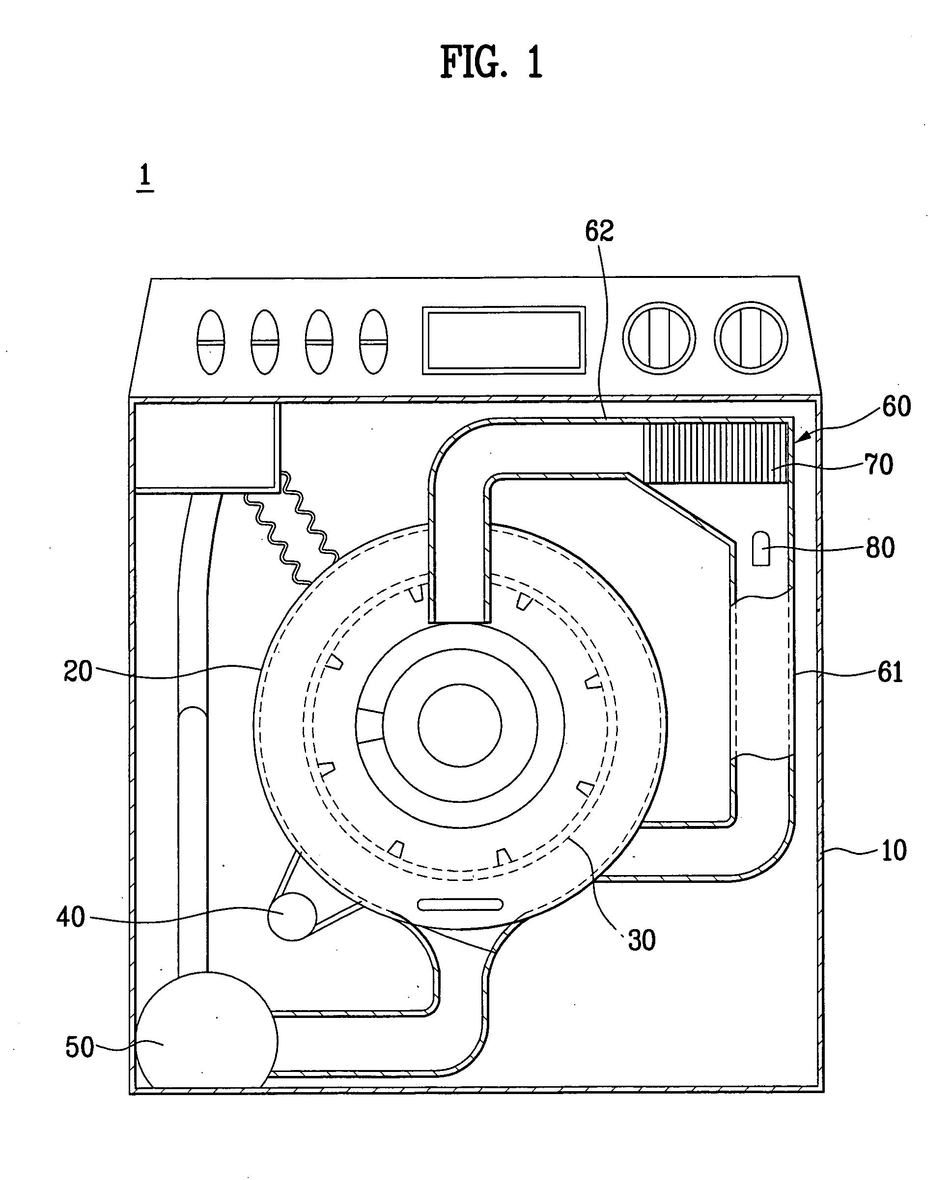
[0050] the present invention will be described with reference to FIG. 1.

[0051] Referring to FIG. 1, the washing machine 1 includes a cabinet 10 forming an exterior of the washing machine 1 having a door mounted on a front thereof, a tub 20 mounted in the cabinet 10, a drum 30 rotatably mounted in the tub 20, a motor 30 for rotating the drum 30, and a drain pump 50 for draining the washing water from the tub 20.

[0052] In addition to this, for drying laundry in the tub 20, in the washing machine, there is a duct 60 having opposite ends connected to the tub 20. The duct 60 includes a drying duct 62 connected to an upper portion of a front of the tub, and a condensing duct 62 connected to a lower portion of a side of the tub.

[0053] In the duct 60, there is a fan 70 for circulating air in the tub 20, and in the condensing duct 61, there is a water supply device 80 for supplying cooling water for condensing moisture in the air in the tub 20.

[0054] The cooling water supplied to the cond...

second embodiment

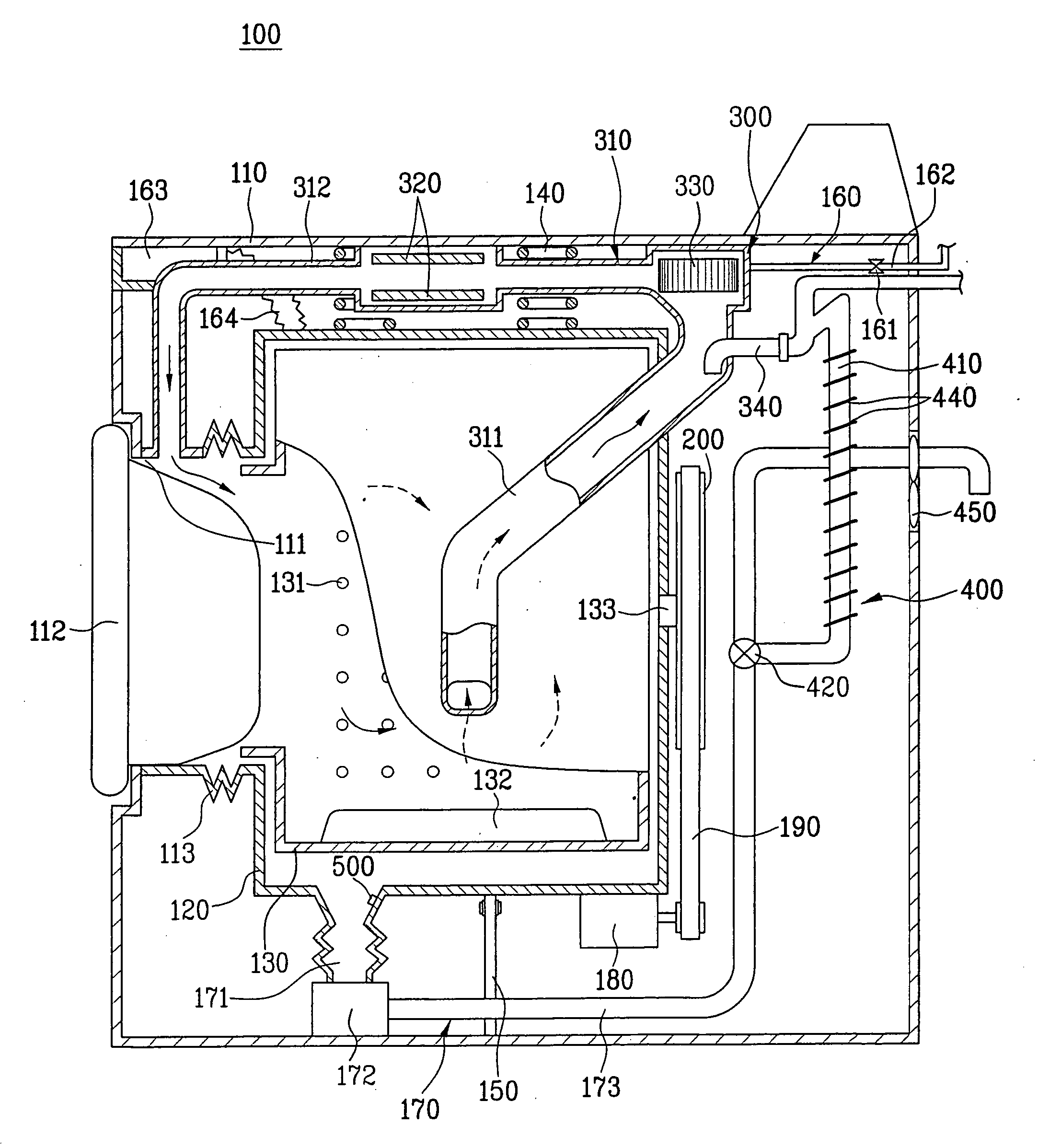
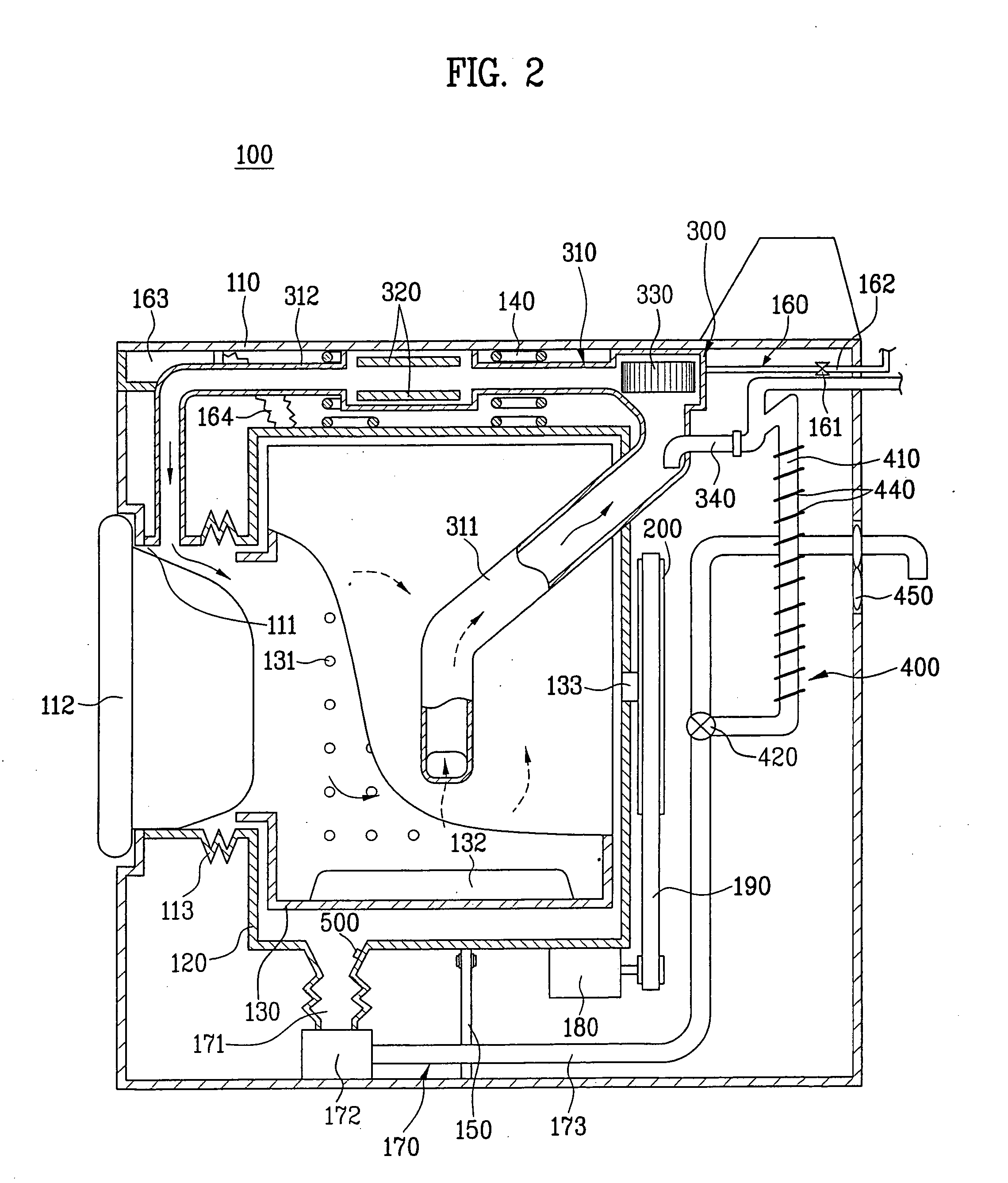
[0057] the present invention will be described with reference to FIG. 2. The washing machine 100 of the present invention includes a cabinet 110 which forms an exterior of the washing machine 100. There is a tub 120 suspended in the cabinet 110. For this, a top of the tub 120 is connected to a spring 140 secured to the cabinet 110, an underside of the tub 120 is connected to a damper 150 hinge coupled to a bottom of the cabinet 110. The spring 140 and the damper 150 not only suspend the tub 120 from the cabinet 110, but also attenuate vibration applied to the tub 120 during operation of the washing machine 100.

[0058] There is a drum 130 rotatably mounted in the tub 120. The drum 130 will be described in more detail.

[0059] The drum 130 has a plurality of pass through holes 131 in an outside circumferential surface, and a plurality of tumbling ribs 132 on an inside circumferential surface. Therefore, water supplied to the tub 120 can move between the drum 130 and the tub 120 through ...

third embodiment

[0079] the present invention will be described with reference to FIG. 3. The washing machine 100 in accordance with a third preferred embodiment of the present invention includes a cabinet 110, a tub 120, a drum 130, and a drying device 300. The drying device 300 includes a duct 310, a fan 330, a water supply device 340, a heater 320, and a cooling water circulating device 400. The cooling water circulating device 400 includes a pump, a circulating hose 410, and a valve 420.

[0080] In description of the third embodiment of the present invention, repetitive description of parts identical to the second embodiment of the present invention will be omitted.

[0081] That is, in the third embodiment of the present invention, the circulating hose 410 has one end connected to the drain hose 173, and the other side connected to the duct 310. In more detail, the circulating hose 410 is connected to an upper portion of the condensing duct 311, for guiding the cooling water from the drain pump 172...


PUM


Abstract

Washing machine including a duct having opposite ends connected to a tub of the washing machine such that air in the tub passes through the duct, and is supplied to the tub again, a fan in the duct for drawing air from an inside of the tub, and discharging to the inside of the tub, a water supply device connected to the duct, for supplying cooling water to the inside of the duct to condense moisture in the air passing through the inside of the duct, a heater in the duct, for heating the air passing through the duct, and a cooling water circulating device for supplying cooling water held at a bottom of the tub after passed through the duct to an inside of the duct, again.

Description

CROSS-REFERENCE TO RELATED APPLICATION [0001] This application claims the benefit of Korean Application No. P2004-24492 filed on Apr. 9, 2004, which is hereby incorporated by reference as if fully set forth herein. BACKGROUND OF THE INVENTION [0002] 1. Field of the Invention [0003] The present invention relates to washing machines, and more particularly, to a washing machine including a drying device for drying laundry in a washing machine. [0004] 2. Discussion of the Related Art [0005] The washing machine, an apparatus for removing dirt from laundry by using action of detergent and water, is one of typical home appliances. The washing machine performs, not only washing, but also drying of washed laundry. [0006] The washing machine heats air and blows the air to a tub, and discharges air from the tub to an outside of the washing machine, to dry the laundry. [0007] Because it is required that the washing machine keeps supplying heated air to the tub, much energy is consumed for heati...

Claims


Application Information

Patent Timeline
Patent Type & Authority Applications(United States)
IPC IPC(8): D06F25/00D06F34/24D06F58/24
CPCD06F25/00D06F58/24D06F2105/08D06F2103/58D06F34/24D06F39/083D06F39/04D06F33/52Y02B40/00
Inventor HONG, SANG WOOKJEON, SI MOON
Owner LG ELECTRONICS INC
Learn More