Snare strainer

a strainer and snare technology, applied in the field of snare strainers, can solve the problems of requiring troublesome work for the human operator, requiring a relatively long time for the replacement of the backside drumhead, and requiring similar troublesome work to replace the existing snare, so as to prevent the parts of the snare strainer from being easily detachable and combined.

Inactive Publication Date: 2005-10-13
YAMAHA CORP
View PDF22 Cites 17 Cited by
  • Summary
  • Abstract
  • Description
  • Claims
  • Application Information

AI Technical Summary

Benefits of technology

[0016] It is an object of the invention to provide a snare strainer adapted to a snare drum, wherein a snappy member can be easily attached to and detached therefrom, and wherein in the replacement of a drumhead, it is unnecessary to greatly readjust the tensions of snares, so that the drumhead can be replaced with another one with ease and within a short period of time.
[0022] In the aforementioned structure, the backside drumhead can be replaced with another drumhead by removing the base fixing portion of the first holding member from the moving base (and by removing the base fixing portion of the third holding member from the second fixing base), wherein it is unnecessary for the human operator to temporarily release the tightly fastened condition of the interconnection member, which is held between the first and second holding members and is also held between the third and fourth holding member. This makes it easy for the human operator to replace the backside drumhead with another one, and this also makes it unnecessary for the human operator to re-adjust the tension that is defined by the positional relationships between the snappy member and the holding members. In addition, the snappy member whose interconnection member is held between the holding members can be collectively replaced with a new one. That is, it is very easy for the human operator to replace the snappy member equipped with the interconnection member and holding members with a new one.
[0023] Due to the provision of the pressing members, it is possible to reliably prevent the interconnection members from being accidentally removed from the holding members because the interconnection member is firmly fixed and engaged into the engagement grooves.
[0025] Due to the provision of the positioning means, it is possible to establish the prescribed positioning between the first holding member and the moving base and between the third holding member and the second fixing base; hence, it is possible to prevent parts of the snare strainer from being unexpectedly dropped or removed when the backside drumhead is replaced with another one. In addition, the positioning means reliably prevents the holding means from being rotated; hence, the paired holding members can be easily detachably combined together by use of a single bolt, a single screw, and the like.

Problems solved by technology

This requires troublesome work for the human operator.
This requires a relatively long time for the replacement of the backside drumhead 3.
Of course, similar troublesome work should be required to replace the existing snares (or the existing snappy member) with other types of snares (or another snappy member).

Method used


Image

  • Snare strainer
  • Snare strainer
  • Snare strainer

Examples


Embodiment Construction

[0040] This invention will be described in further detail by way of examples with reference to the accompanying drawings.

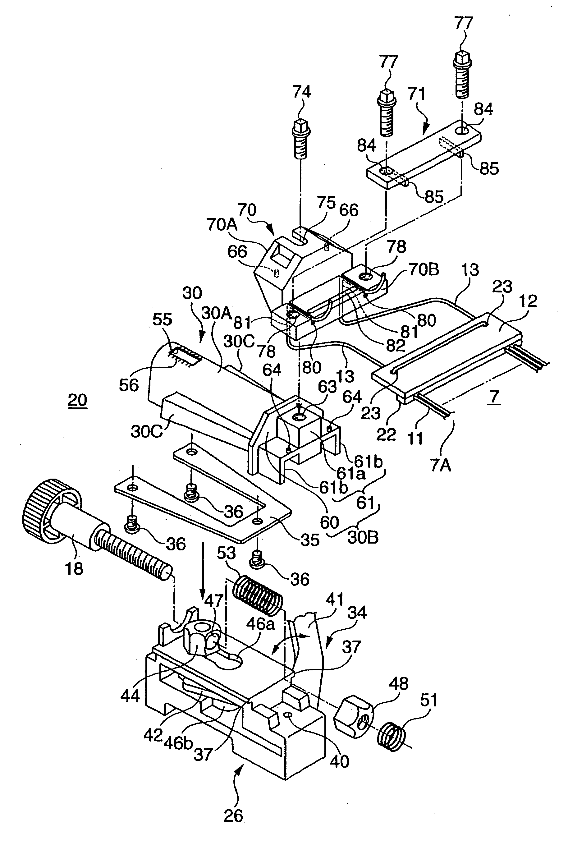
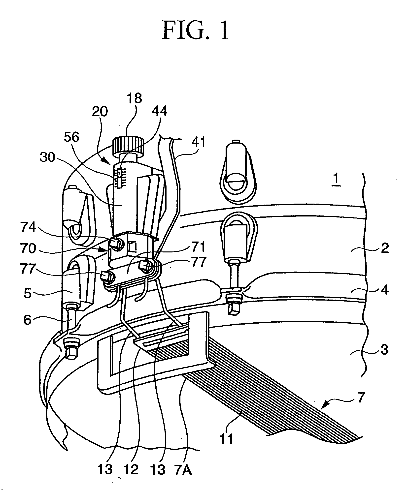
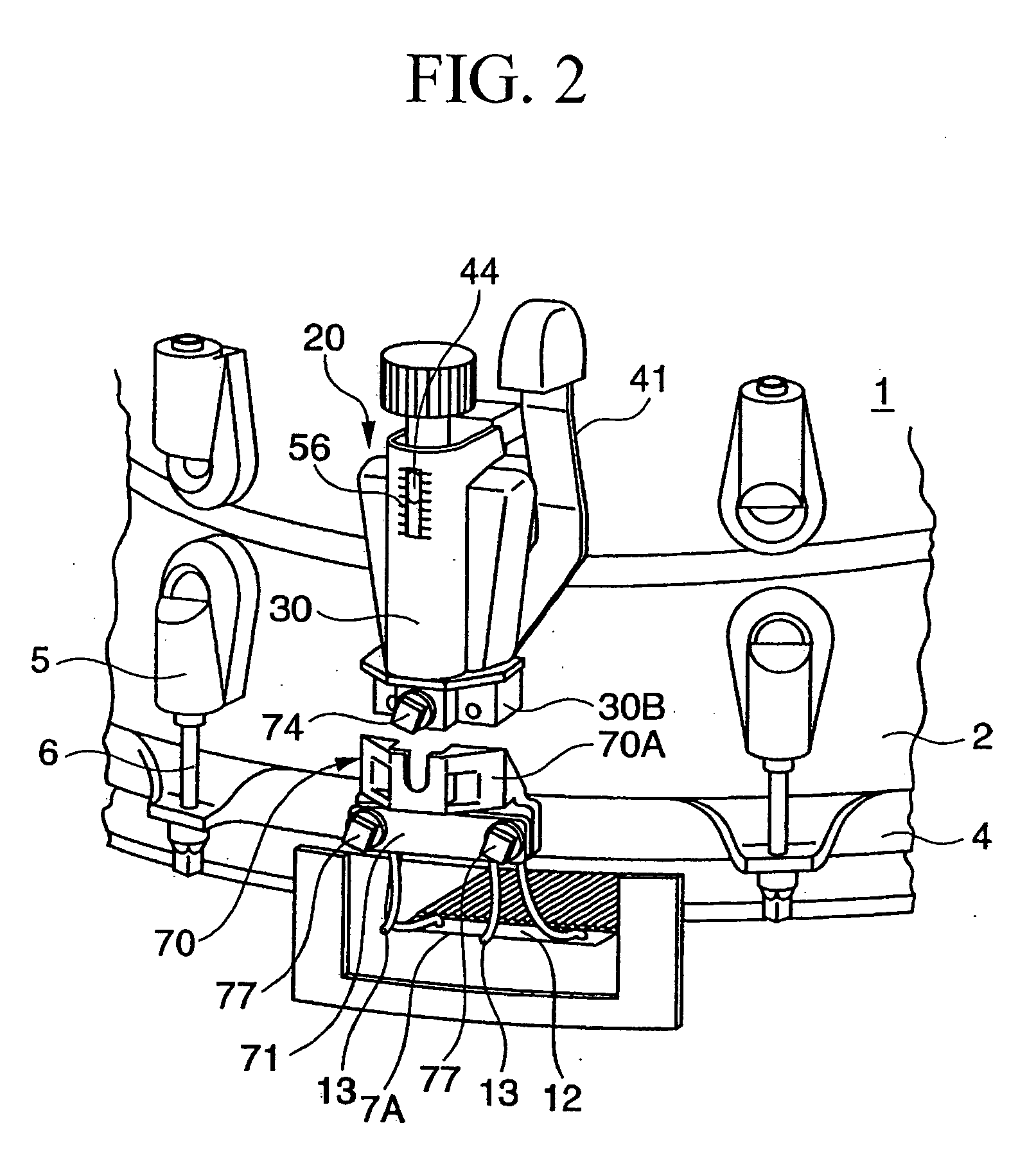
[0041]FIGS. 1, 2, 3, 4A-4C, 5A-5C, 6, and 7 show illustrations regarding a snare strainer adapted to a snare drum in accordance with a preferred embodiment of the invention, wherein parts identical to those shown in FIGS. 8 and 9 are designated by the same reference numerals. Specifically, FIG. 1 is a perspective view showing essential parts of a snare drum in which a moving end of a snappy member is interconnected with a first strainer; FIG. 2 is a perspective view showing essential parts of the snare drum in which the moving end of the snappy member is released from the interconnected state with the first strainer; FIG. 3 is an exploded perspective view showing essential parts of the first strainer; FIG. 4A is a front view of the first strainer; FIG. 4B is a cross-sectional view taken along line A-A in FIG. 4A; FIG. 4C is a bottom view of the first strainer; FI...


PUM


Abstract

A snare strainer adapted to a snare drum comprises first and second strainers, which are attached to opposite positions on the exterior circumferential surface of a drum cylinder and by which a snappy member including snares is controlled to move in close contact with or separate from the backside drumhead upon operation of a switch mechanism. One end of an interconnection member included in the snappy member is held between first and second holding members of the first strainer, and the other end is held between third and fourth holding members of the second strainer. A tension adjustment screw is operated to adjust tension applied to the snappy member, which can be visually observed using the scale. Hence, it is easy for the human operator to attach and replace the snappy member and to replace the backside drumhead with another drumhead in a short period of time.

Description

BACKGROUND OF THE INVENTION [0001] 1. Field of the Invention [0002] This invention relates to snare strainers that control snappy members including snares to move in close contact with or separate from drumheads of snare drums. [0003] This application claims priority on Japanese Patent Application No. 2004-7151, the content of which is incorporated herein by reference. [0004] 2. Description of the Related Art [0005] Snare drums produce special sound effects called tumbling effects, wherein snappy members including a plurality of thin snares are controlled to move in close contact with or separate from backside drumheads (corresponding to non-striking sides of snare drums), or they are controlled to move in close contact with or separate from both of backside drumheads and front-side drumheads (corresponding to striking sides of snare drums), so that vibrations of drumheads are transmitted to snares to produce pattering or rattling sounds having light tone colors. The following docum...

Claims


Application Information

Patent Timeline
Patent Type & Authority Applications(United States)
IPC IPC(8): G10D13/02G10D13/00
CPCG10D13/025G10D13/18G10D13/02
Inventor HAGIWARA, TAKASHIISHIMATSU, NORIHIKO
Owner YAMAHA CORP
Why Eureka
Try Eureka