Reciprocating engine

Inactive Publication Date: 2005-10-13
BANDO KIKO CO LTD
View PDF4 Cites 6 Cited by
  • Summary
  • Abstract
  • Description
  • Claims
  • Application Information

AI Technical Summary

Benefits of technology

[0043] According to the invention, it is possible to provide a reciprocating engine which makes it possible to reliably prevent the leakage of the combustion gases introduced into the thrust side space, effectively obta

Problems solved by technology

In consequence, the combustion gases introduced into the thrust side space can leak into the anti-thrust side space through the gap, and the gas pressure can become insufficient, causing the piston to fail to float from the inner surface of the cylinder in the combustion stroke.
Thus, there is a possibility that it is impossi

Method used


Image

  • Reciprocating engine
  • Reciprocating engine
  • Reciprocating engine

Examples


Example

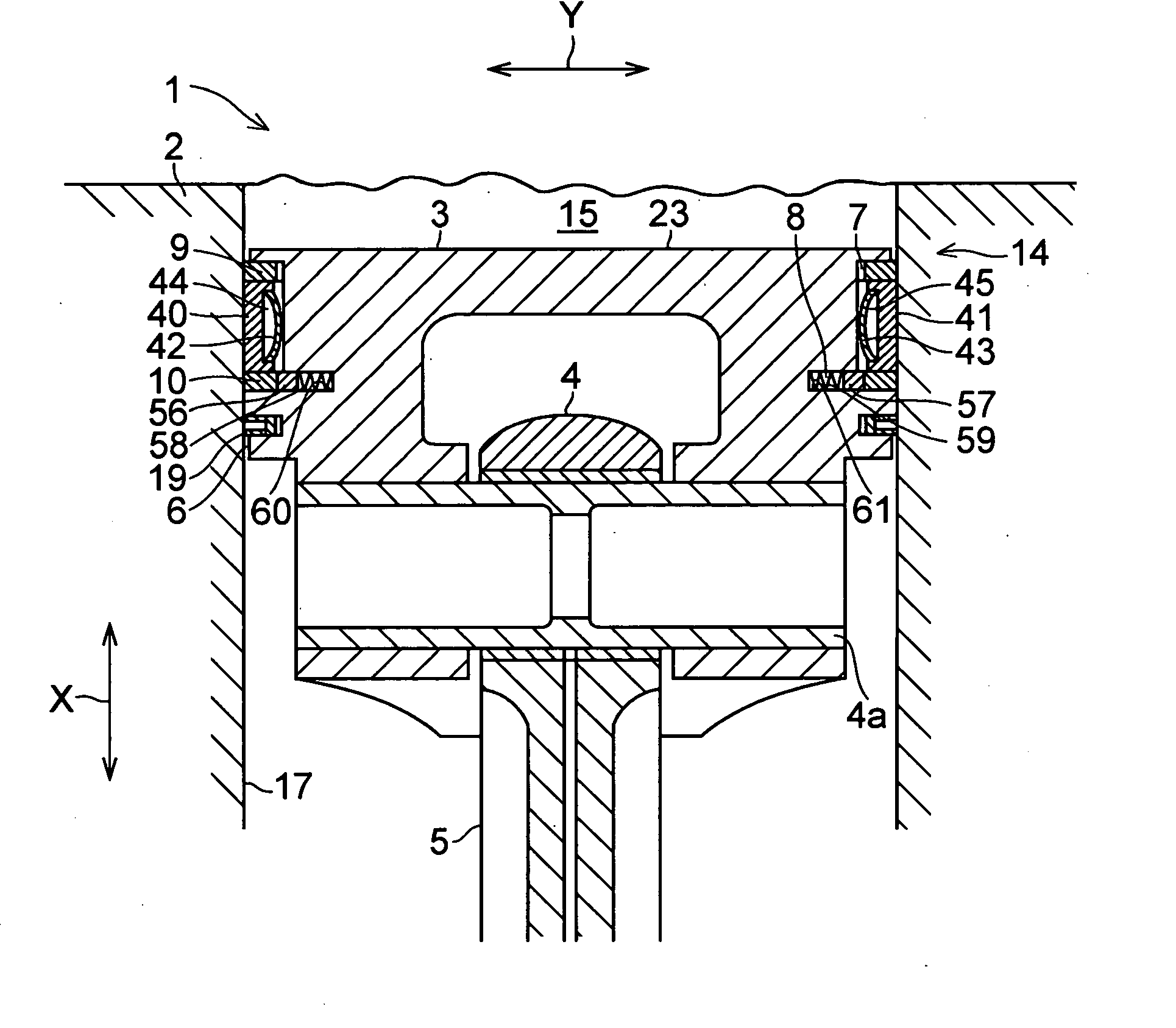
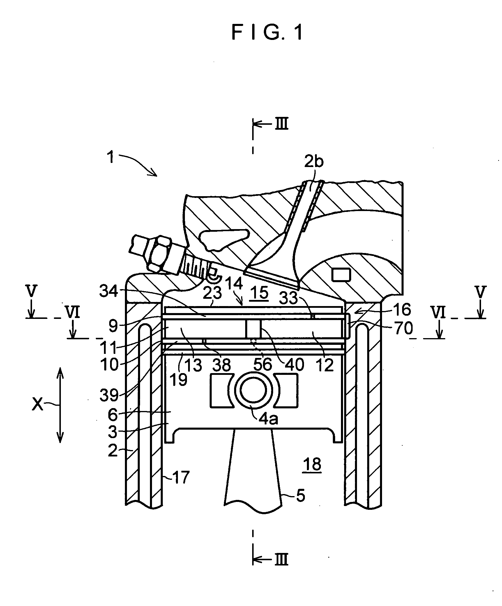
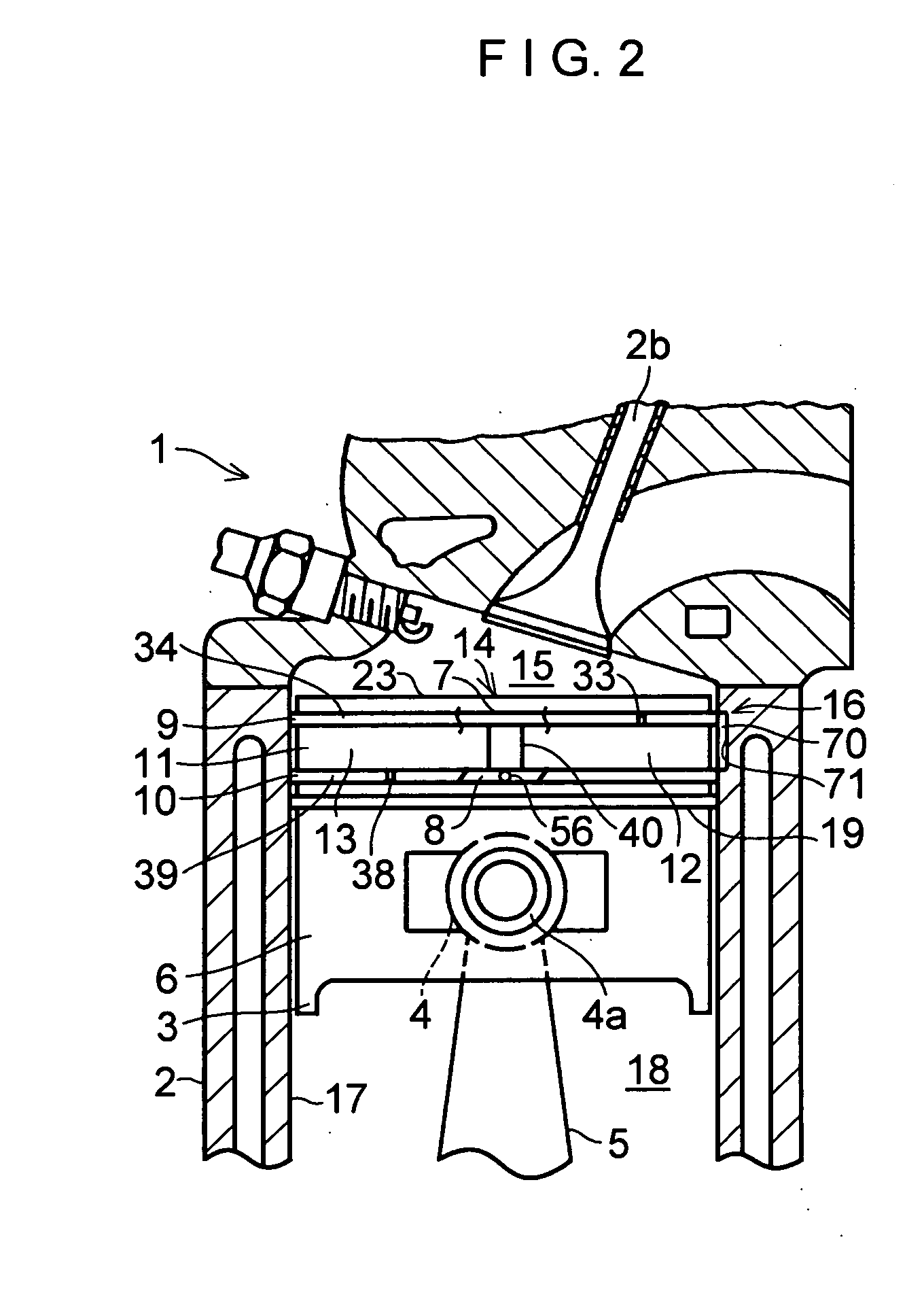
[0058] In FIGS. 1 to 8, a four-cycle reciprocating engine (four-cycle gasoline engine) 1 in accordance with this embodiment is comprised of a cylinder 2; a piston 3 reciprocating in the cylinder 2 in a direction X; a connecting rod 5 rotatably coupled at its small end portion 4 to the piston 3 through a piston pin 4a; ring grooves 7 and 8 disposed adjacent to each other in the direction X and formed in a peripheral side surface 6 of the piston 3; piston rings 9 and 10 respectively fitted in the ring grooves 7 and 8; a partitioning means 14 for partitioning an annular space 11 between the piston rings 9 and 10 into a thrust side semiannular space 12 and an anti-thrust side semiannular space 13; and a communicating means 16 for allowing the space 12 to communicate with a combustion chamber 15 where a fuel-air mixture is burned.

[0059] The cylinder 2 has a cylindrical space 18 defined by its inner surface 17, and the piston 3 is disposed in the space 18 so as to be reciprocatable in th...


PUM


Abstract

A reciprocating engine (1) includes a cylinder (2); a piston (3) reciprocating in the cylinder (2) in a direction X; a connecting rod (5) rotatably coupled at its small end portion (4) to the piston (3) through a piston pin (4a); ring grooves (7, 8) disposed adjacent to each other in the direction X and formed in a peripheral side surface (6) of the piston (3); piston rings (9, 10) respectively fitted in the ring grooves (7, 8); partitioning means (14) for partitioning an annular space (11) between the piston rings (9, 10) into a thrust side semiannular space (12) and an anti-thrust side semiannular space (13); and communicating means (16) for allowing the space (12) to communicate with a combustion chamber (15) where a fuel-air mixture is burned.

Description

TECHNICAL FIELD [0001] The present invention relates to a reciprocating engine. BACKGROUND ART [0002] In a reciprocating engine, a technique has been proposed in which, to reduce sliding frictional resistance between a cylinder and a piston in the reciprocating motion of the piston, a gas chamber, into which combustion gases from a combustion chamber are introduced and in which they are stored, is formed between an inner surface of the cylinder and a side surface of the piston opposing this inner surface. The piston is caused to float from the inner surface of the cylinder by the gas pressure of the combustion gases in this gas chamber, thereby reducing the sliding frictional resistance between the inner surface of the cylinder and the side surface of the piston in the reciprocating motion of the piston. As one example of such a proposed reciprocating engine, there is an engine in which an annular space is formed between a first piston ring disposed adjacent to an upper surface of t...

Claims


Application Information

Patent Timeline
IPC IPC(8): F02F5/00F02B19/10F02B19/00F02F3/00F16J9/06F02B23/08F02B23/00F16J1/00F02F1/18F02F1/00
CPCF02B19/108F02B23/08F02B2019/002F02F1/18F02F3/00F16J1/001F16J9/061F16J9/063F02B23/00F02F5/00
Inventor BANDO, SHIGERU
Owner BANDO KIKO CO LTD
Why Eureka
Try Eureka