
Color OLED with added color gamut pixels

Active Publication Date: 2005-10-13
GLOBAL OLED TECH
View PDF14 Cites 276 Cited by
  • Summary
  • Abstract
  • Description
  • Claims
  • Application Information

AI Technical Summary

Benefits of technology

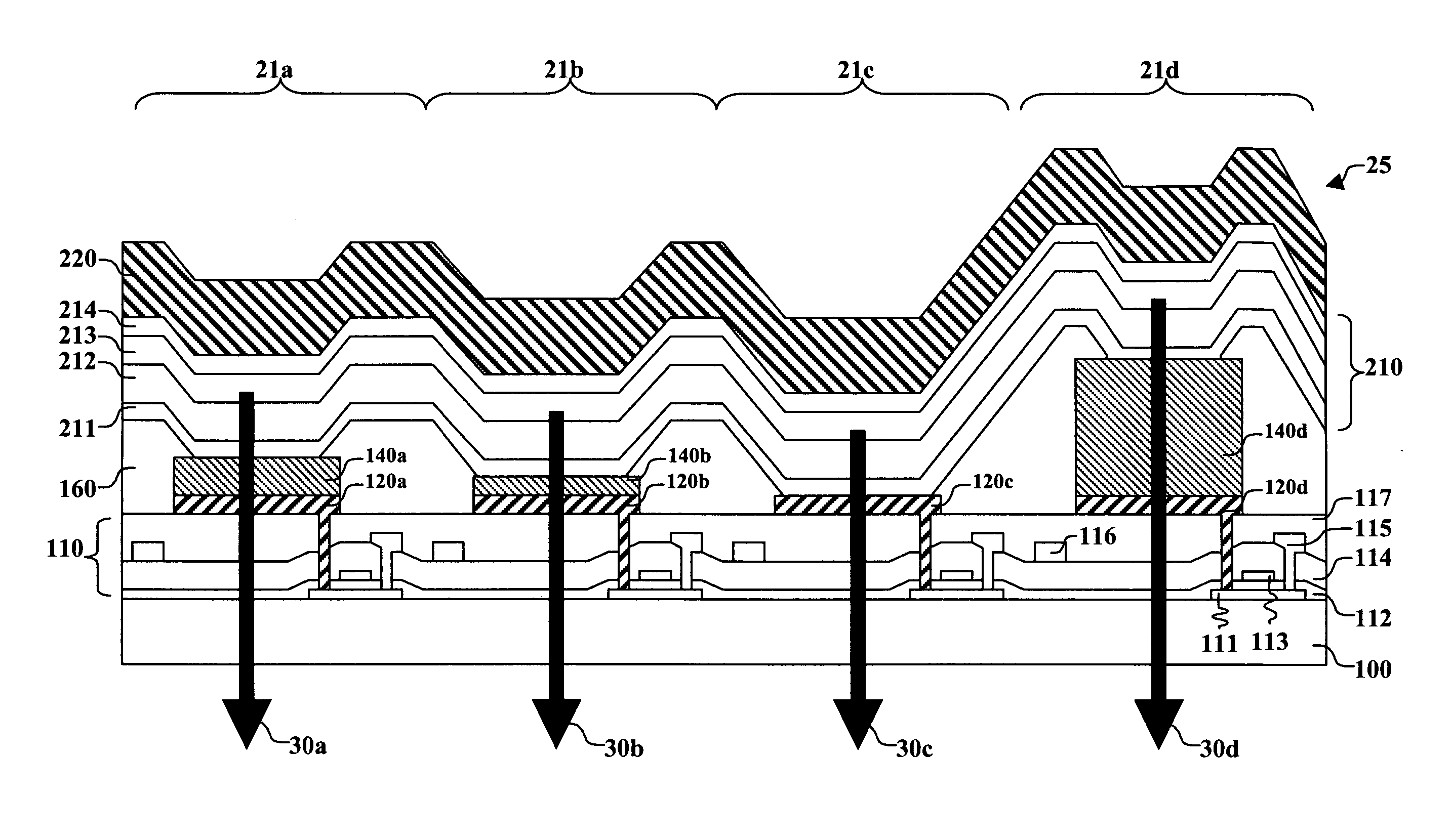
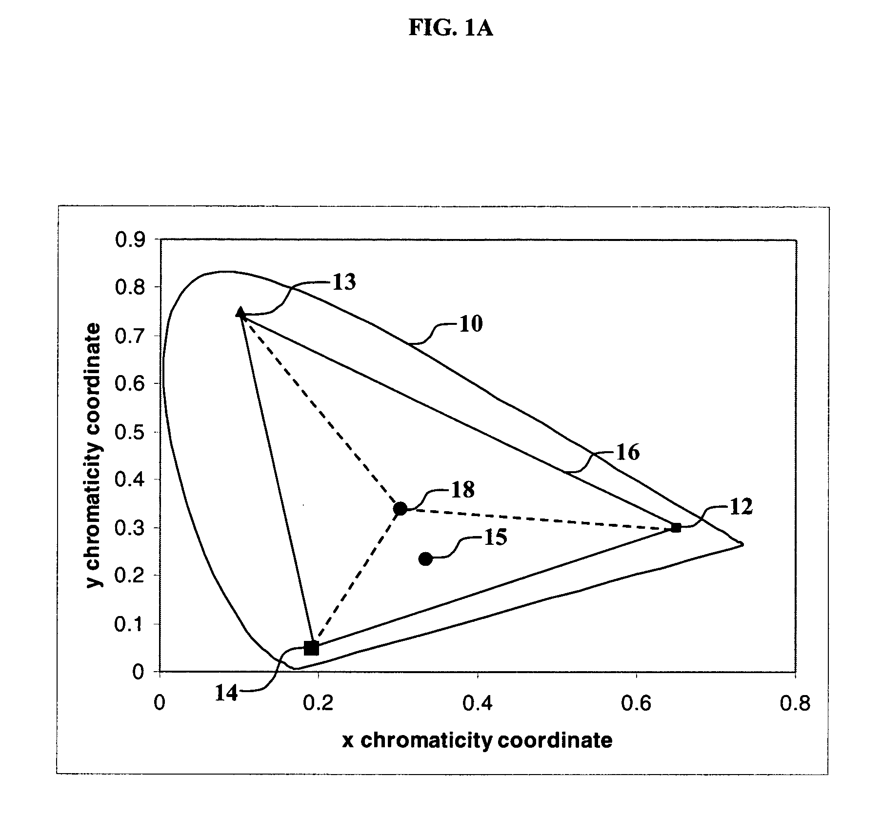
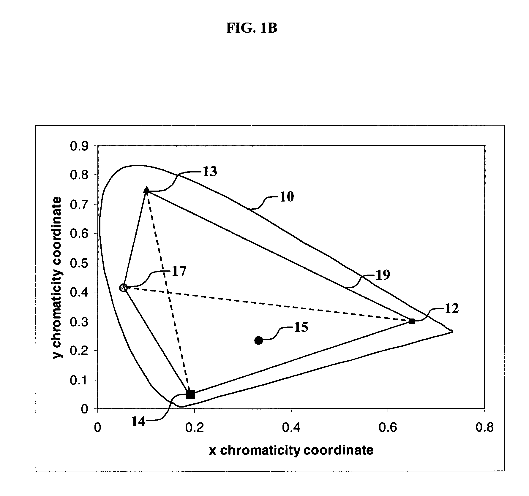
[0012] It is an advantage of the present invention that it provides improved device efficiency with lower power consumption and longer lifetime. It is a further advantage for some embodiments of the present invention that such a device can be constructed using common OLED organic layers for all pixels which does not require precision patterning of organic materials to form the pixels. Any device patterning necessary can be done as part of the formation of the active matrix components or passive matrix components by photolithographic methods, which are more precise methods than those commonly used to deposit organic layers. It is a further advantage for some embodiments of the present invention that such a device can be constructed without the need for color filter elements, which thereby lowers cost. It is a further advantage for some embodiments of the present invention that an improved or extended color gamut is provided. This configuration permits for an RGBW (red, green, blue, and white) or RGBX (red, green, blue, and at least one additional color) configuration to be used in a top-emitting device with a highly conductive cathode that does not require patterning.
that it provides improved device efficiency with lower power consumption and longer lifetime. It is a further advantage for some embodiments of the present invention that such a device can be constructed using common OLED organic layers for all pixels which does not require precision patterning of organic materials to form the pixels. Any device patterning necessary can be done as part of the formation of the active matrix components or passive matrix components by photolithographic methods, which are more precise methods than those commonly used to deposit organic layers. It is a further advantage for some embodiments of the present invention that such a device can be constructed without the need for color filter elements, which thereby lowers cost. It is a further advantage for some embodiments of the present invention that an improved or extended color gamut is provided. This configuration permits for an RGBW (red, green, blue, and white) or RGBX (red, green, blue, and at least one additional color) configuration to be used in a top-emitting device with a highly conductive cathode that does not require patterning.

Problems solved by technology

This results in improved power consumption relative to an RGB constructed of similar OLED materials.

Method used


Image

  • Color OLED with added color gamut pixels
  • Color OLED with added color gamut pixels
  • Color OLED with added color gamut pixels

Examples


Embodiment Construction

[0023] The term “OLED device” or “organic light-emitting display” is used in its art-recognized meaning of a display device comprising organic light-emitting diodes as pixels. A color OLED device emits light of at least one color. The term “multicolor” is employed to describe a display panel that is capable of emitting light of a different hue in different areas. In particular, it is employed to describe a display panel that is capable of displaying images of different colors. These areas are not necessarily contiguous. The term “full color” is employed to describe multicolor display panels that are capable of emitting in several regions of the visible spectrum and therefore displaying images in a large combination of hues. The red, green, and blue colors constitute the three primary colors from which all other colors can be produced by appropriate mixing. However, for this invention, full color can include additional different color pixels whose purpose will become clear. The term ...


PUM


Abstract

An OLED device includes an array of light-emitting pixels having organic layers, including at least one emissive layer that produces light and spaced electrodes, and wherein at least three pixels produce colors which define a color gamut and at least one pixel produces light within the color gamut, and wherein the at least one pixel within the color gamut includes a reflector and a semitransparent reflector which function to form a microcavity.

Description

CROSS REFERENCE TO RELATED APPLICATIONS [0001] Reference is made to commonly assigned U.S. patent application Ser. No. ______ filed concurrently herewith by Michael L. Boroson et al., entitled “OLED With Color Change Media”, the disclosure of which is herein incorporated by reference.FIELD OF THE INVENTION [0002] The present invention relates to organic electroluminescent (EL) devices. More specifically, this invention relates to a multicolor emitting EL device with improved stability, efficiency, and color purity. BACKGROUND OF THE INVENTION [0003] Full color organic electroluminescent (EL), also known as organic light-emitting devices (OLED), have been demonstrated recently as a new type of flat panel display. OLED devices are attractive because of their low driving voltage, high luminance, wide-angle viewing, and capability for full color flat emission displays. In simplest form, an organic EL device is comprised of an anode for hole injection, a cathode for electron injection, a...

Claims


Application Information

Patent Timeline
IPC IPC(8): H05B33/00
CPCH01L27/3213H01L51/5265H10K59/30H10K59/351H10K59/876H10K50/852
Inventor BOROSON, MICHAEL L.WINTERS, DUSTIN L.TYAN, YUAN-SHENG
Owner GLOBAL OLED TECH
Learn More