Beam forming array of transducers

a beam-forming array and transducer technology, applied in the direction of antennas, frequency/directions obtaining arrangements, microphone signal combinations, etc., can solve the problem of substantial risk of array damage during transport and handling, and achieve the effect of simplifying manufacturing and handling and detecting easily damaged arms

Inactive Publication Date: 2005-10-13
BRUEL & KJAER SOUND & VIBRATION MEASUREMENT
View PDF8 Cites 23 Cited by
  • Summary
  • Abstract
  • Description
  • Claims
  • Application Information

AI Technical Summary

Benefits of technology

[0012] According to the invention this object is achieved by arranging the transducers in each sub-array on a straight line. A straight line is the simplest possible geometry to manufacture. When such a linear sub-array is manufactured as rods or arms, which possibly are detachable, deviations from the prescribed linear geometry can easily be detected by visual inspection. Possible damage to arms can easily be detected, and damaged arms can be replaced or repaired. All sub-arrays being identical further simplifies the manufacturing and handling.

Problems solved by technology

Transporting such large arrays safely to and from the site of use is a challenge, and the risk of the array being damaged during transport and handling is substantial.

Method used


Image

  • Beam forming array of transducers
  • Beam forming array of transducers
  • Beam forming array of transducers

Examples


Embodiment Construction

[0029] The invention will be described with microphones used as the preferred transducers.

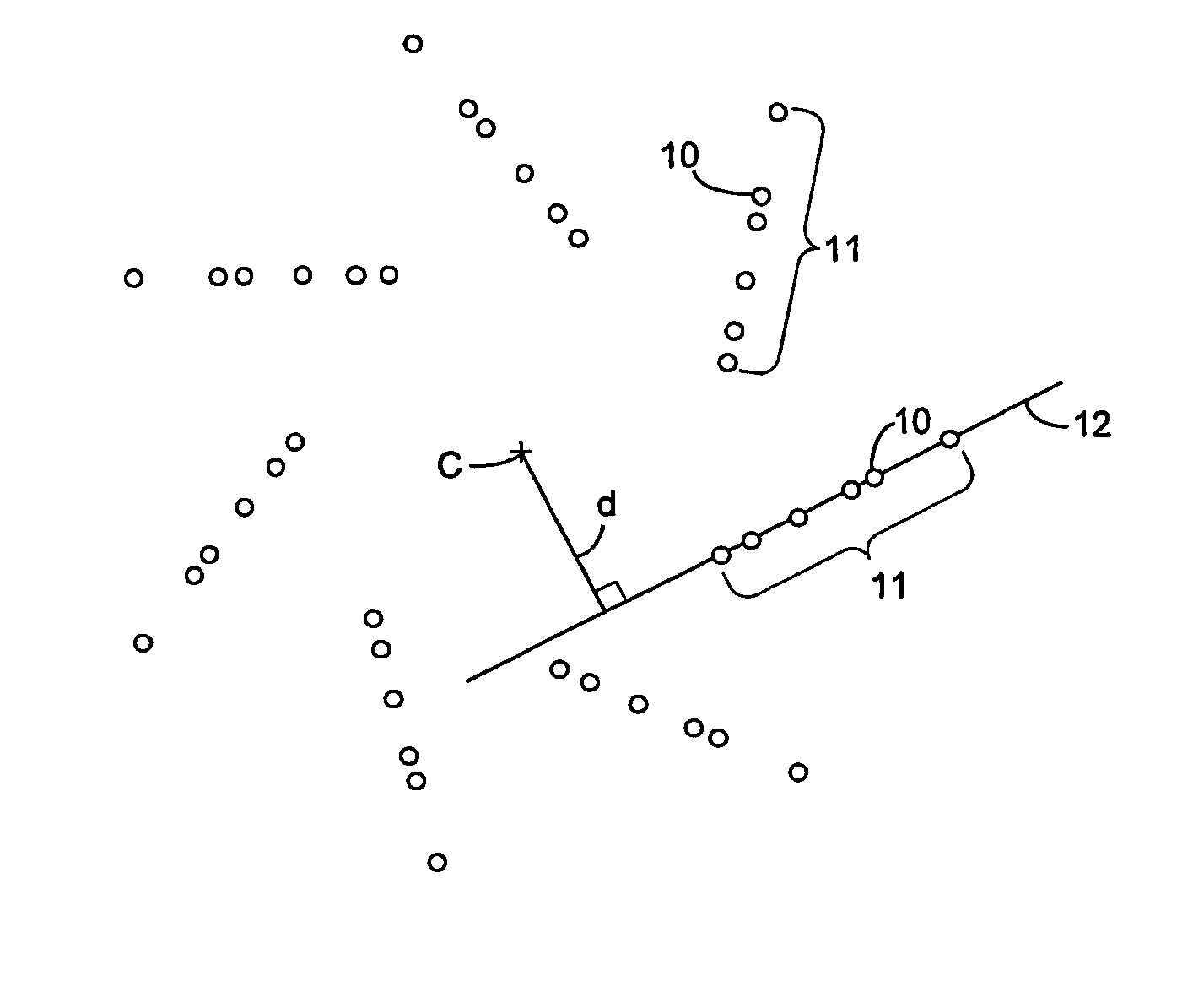
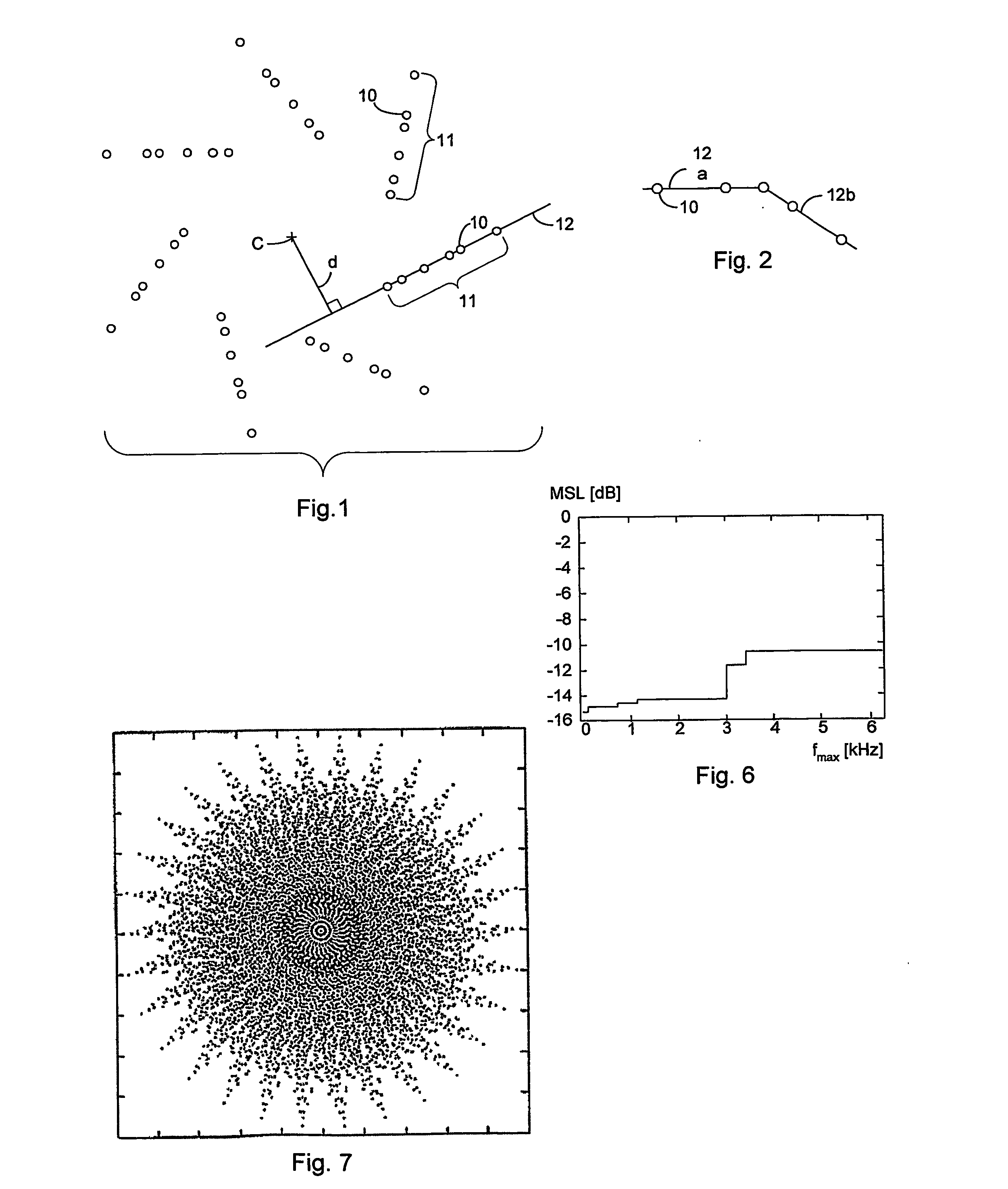
[0030]FIG. 1 shows a planar, ie two-dimensional, array of microphones 10, where the idealised position of each microphone 10 is marked with a circle. The microphones preferably have uniform physical and acoustical properties, and the microphones 10 are arranged in sub-arrays 11. In the shown embodiment there are seven sub-arrays 11 with six microphones 10 in each sub-array. In each sub-array 11 the microphones 10 are arranged on a straight line 12. The sub-arrays 11 are distributed uniformly around a common centre C, so that rotational or circular symmetry about the common centre C is obtained. Circular symmetry means that the structure repeats itself an integer number of times when rotated through 360 degrees around the centre C. In the shown embodiment with seven sub-arrays the structure repeats it self by rotation through an angle of 360 / 7 degrees or any integer multiple thereof. The straig...


PUM


Abstract

A two-dimensional array of a plurality of transducers comprising a first plurality of like sub-arrays (11, 11a, 11b) of transducers (10) in a circularly symmetric arrangement around a common centre (C), where the transducers in each sub-array of the first plurality have individual distances from the common centre that form a progressive series of distances with a first lower limit and a first upper limit. Each sub-array in the first plurality of sub-arrays comprises at least three transducers arranged on a first straight line (12), and the first straight line is offset laterally a first distance (d) from the common centre. The number of sub-arrays is odd, and the sub-arrays may be separate units that can be selectively assembled to form the two-dimensional array and selectively disassembled.

Description

FIELD OF THE INVENTION [0001] The present invention relates to planar or two-dimensional arrays of a plurality of transducer elements. More specifically, the invention relates to such arrays comprising a first plurality of like sub-arrays of transducers in a circularly symmetric arrangement around a common centre, where the transducers in each sub-array of the first plurality have individual distances from the common centre that form a progressive series of distances. BACKGROUND OF THE INVENTION [0002] Such arrays of transducers are used as phased arrays for focusing the sensitivity of the array in a desired direction. Preferably, the array should be usable in a broad frequency range. Phased arrays are usable as receiving arrays, eg for locating a signal source or for producing a two-dimensional image of one or more point sources or distributed sources, or for selecting signals from a particular source and excluding or attenuating signals from other sources. Phased arrays are also u...

Claims


Application Information

Patent Timeline
Patent Type & Authority Applications(United States)
IPC IPC(8): H01Q3/26H01Q21/06H01Q21/22H04R1/32H04R1/40H04R3/00H04R3/12
CPCH01Q3/26H01Q21/061H01Q21/22H04R1/403H04R2430/20H04R3/005H04R3/12H04R2201/401H04R2201/405H04R1/406
Inventor CHRISTENSEN, JACOB JUHLHALD, JORGEN
Owner BRUEL & KJAER SOUND & VIBRATION MEASUREMENT
Why Eureka
Try Eureka