
Self-calibration for an eye tracker

a self-calibration and eye tracking technology, applied in the field of calibration, can solve the problems of eye gaze tracking techniques, difficult calibration of devices, and bulky and cumbersome eye tracking devices and calibration systems

Active Publication Date: 2005-10-13
HEWLETT PACKARD DEV CO LP
View PDF22 Cites 91 Cited by
  • Summary
  • Abstract
  • Description
  • Claims
  • Application Information

AI Technical Summary

Benefits of technology

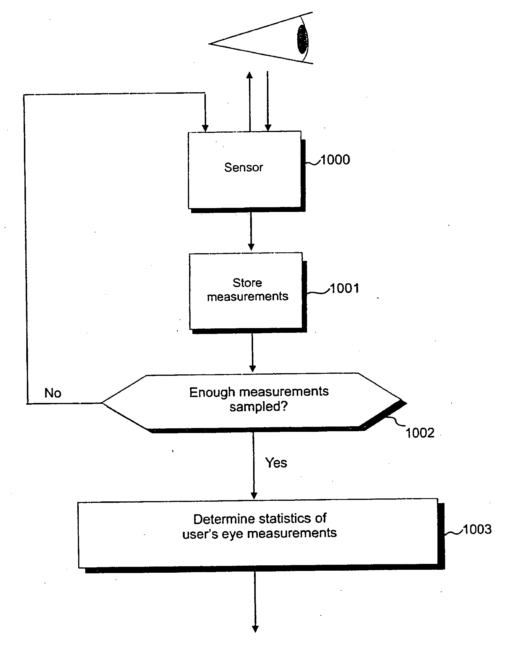
[0027] According to a second aspect there is provided a method of automatic calibration of an eye tracking system, said method comprising: capturing a plurality of eye measurements, wherein each said eye measurement relates to a corresponding eye gaze position of a human eye; determining a set of statistics data from said plurality of eye gaze measurements; comparing said set of statistics of said eye gaze measurements with a set of statistics relating to a plurality of pre-measured eye gaze positions of at least one person; and, as a result of said comparison, determining a calibration correction factor which, when applied to said statistics of said eye gaze measurement, give an optimum match between said statistics of eye gaze measurement and said statistics of predetermined eye gaze positions.

Problems solved by technology

However, such known eye tracking devices and calibration systems tend to be bulky and cumbersome, and typically, the camera sensor is positioned away from the user at a fixed position in a room.
However, one of the well known problems in using eye motion for controlling wearable computers, wearable cameras, user interfaces and the like, is that calibration of the devices is difficult.
Known eye gaze tracking techniques suffer from problems concerning head movement, over-sensitive tracking sensors, and equipment that loses calibration easily and quickly.
Tracking data tokenization: Raw eye tracking data often contains entirely wrong coordinates, because the tracker has missed a video frame, or a user has blinked, causing discontinuity in data.
Momentary spikes in raw data are interpreted as faulty measurements.
General known problems associated with developing eye gaze systems include: Size and bulkiness of equipment; Eye tracking equipment is over-sensitive to movement of a user; Eye tracking equipment currently requires constant user attended recalibration; Eye tracking equipment must be able to track several persons simultaneously because people work in groups together; The problem of iris pattern recognition is not solved, and therefore current known eye tracking equipment cannot identify tracked persons; Eye tracking equipment is not currently personalized enough to store preferences and characteristics of individual user persons.
Consequently, known calibration techniques are difficult to apply to commercially viable products which rely on eye tracking for their control or operation.

Method used


Image

  • Self-calibration for an eye tracker
  • Self-calibration for an eye tracker
  • Self-calibration for an eye tracker

Examples


Embodiment Construction

[0045] There will now be described by way of example a specific mode contemplated by the inventors. In the following description numerous specific details are set forth in order to provide a thorough understanding. It will be apparent however, to one skilled in the art, that the present invention may be practiced without limitation to these specific details. In other instances, well known methods and structures have not been described in detail so as not to unnecessarily obscure the description.

[0046] In this specification, the term “vision controlled device” is used to mean any vision controlled computer entity which is controlled by a human user's eye movements.

[0047] In this specification, the term “wearable computer entity” is used to describe any human portable computer device, including but not limited to wearable cameras.

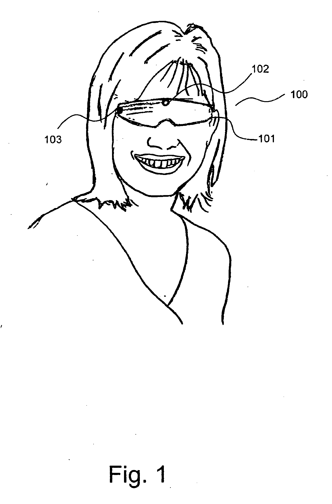
[0048] Referring to FIG. 1 herein, there is illustrated schematically one example of a vision controlled device, in this case a wearable camera device, in...


PUM


Abstract

Automatic calibration of an eye tracking system involves capturing a plurality of eye measurements, wherein each said eye measurement relates to a corresponding eye gaze position of a human eye; determining a set of statistics data from said plurality of eye gaze measurements; comparing said set of statistics of said eye gaze measurements with a set of statistics relating to a plurality of pre-measured eye gaze positions of at least one person; and as a result of said comparison, determining a calibration correction factor which, when applied to said statistics of said eye gaze measurement, give an optimum match between said statistics of eye gaze measurement and said statistics of predetermined eye gaze positions.

Description

TECHNICAL FIELD [0001] The present invention relates to calibration, and particularly although not exclusively, to the calibration of wearable computing entities and / or wearable cameras. CLAIM TO PRIORITY [0002] This application claims priority to copending United Kingdom utility application entitled, “SELF-CALIBRATION FOR AN EYE TRACKER,” having serial no. GB 0406710.4, filed Mar. 25, 2004, which is entirely incorporated herein by reference. BACKGROUND [0003] It is known in several fields of computing, for example of the fields of wearable computers, and for computer user interfaces, that control of computers or computer activated devices can be achieved by monitoring human eye movements, including eye gaze direction. [0004] Prior art eye tracking devices are known in the fields of psychological research. One such known device comprises a white screen having a predetermined pattern of dots, which a user views. An eye tracking device having a camera sensor tracks the user's eye move...

Claims


Application Information

Patent Timeline
IPC IPC(8): A61B3/113A61B3/14G06F3/00G06F3/01
CPCG06F3/013A61B3/113G06V40/19
Inventor PILU, MAURIZIO
Owner HEWLETT PACKARD DEV CO LP
Learn More