Quantitative echo souner and method of quantitative sounding of fish

a quantitative echo and sounding technology, applied in the field of splitbeam type quantitative echo sounders and splitbeam type can solve the problems of increasing measurement errors, measuring errors in quantitative fish echo sounding, and difficult to determine the strength ts of a single fish when the vessel is in motion, so as to achieve precise quantitative measurement of underwater targets.

Active Publication Date: 2005-10-13
FURUNO ELECTRIC CO LTD
View PDF0 Cites 23 Cited by
  • Summary
  • Abstract
  • Description
  • Claims
  • Application Information

AI Technical Summary

Benefits of technology

[0010] Intended to solve the aforementioned problems of the prior art, the present invention has as an object the provision of a split-beam type quantitative echo sounder and a method of split-beam type quantitative fish echo sounding which make it possible to carry out precise quantitative measurement of underwater targets even when a vessel is in motion due to waves or wind, for instance.

Problems solved by technology

Such a deviation of the target fish from the acoustic axis of the transducer conventionally causes of a measurement error in quantitative fish echo sounding.
The method of correcting measurement errors proposed in Japanese Patent Application Publication No. 1994-160522 however has a problem that it is difficult to determine the target strength TS of a single fish when the vessel is in motion (pitches, rolls or heaves) due to waves or wind, for instance, because this method does not make it possible to freely vary the directions of transmitting and receiving beams to make up for movements of the vessel.
For this reason, there arises a problem that measurement errors increase if the target strength TS is corrected by the angles of incidence of the incoming echo signals determined based on the time differences among the echo signals picked up by the receiving beams formed by the individual vibrating element groups.

Method used


Image

  • Quantitative echo souner and method of quantitative sounding of fish
  • Quantitative echo souner and method of quantitative sounding of fish
  • Quantitative echo souner and method of quantitative sounding of fish

Examples


Embodiment Construction

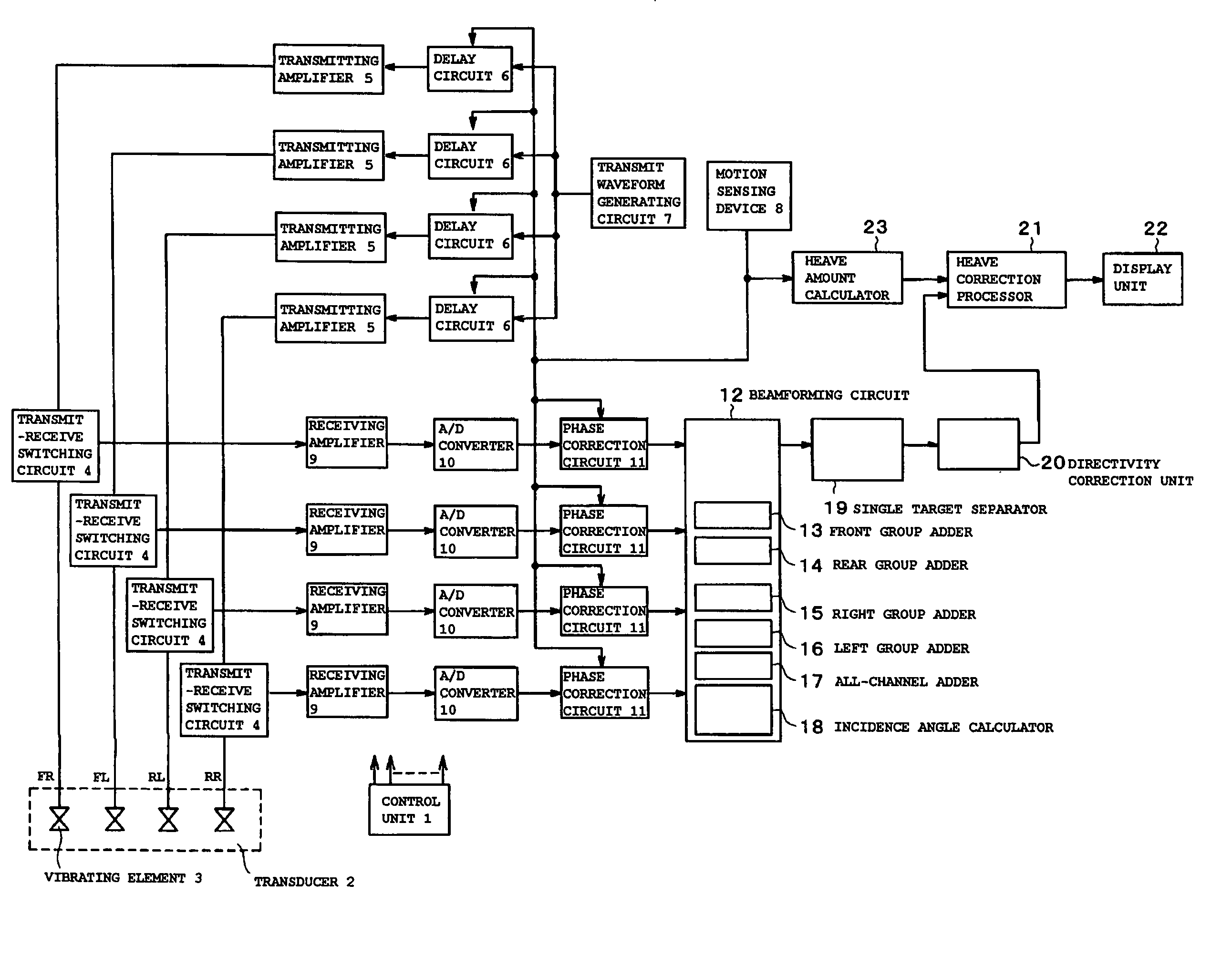
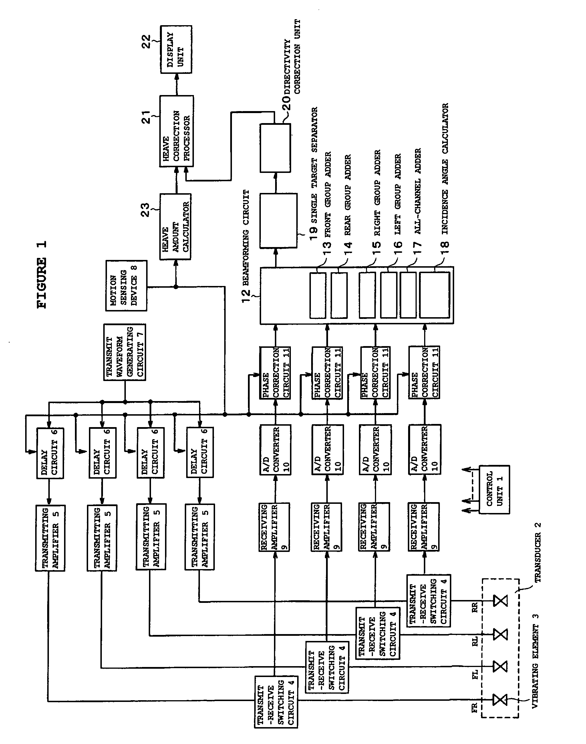
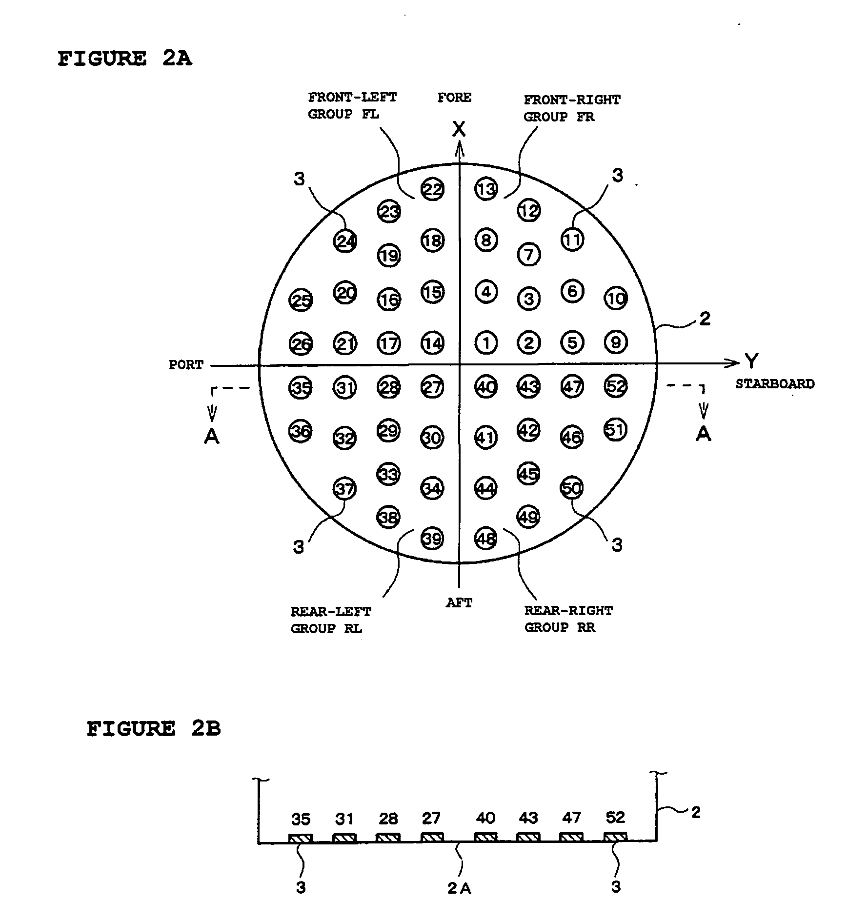
[0038] A split-beam type quantitative echo sounder according to a specific embodiment of the present invention is now described with reference to FIGS. 1, 2A, 2B and 3. FIG. 1 is a block diagram generally showing the configuration of the quantitative echo sounder, FIGS. 2A and 2B are diagrams showing the structure of a transducer 2, and FIG. 3 is a diagram showing an XYZ coordinate system in which the transducer 2 is placed and a beam vector (sounding direction) thereof.

[0039] First, the structure of the transducer 2 is explained referring to FIGS. 2A and 2B. FIG. 2A is a plan view of the transducer 2 and FIG. 2B is sectional view of the transducer 2 taken along lines A-A of FIG. 2A. As can be seen from FIGS. 2A and 2B, the transducer 2 has a flat-shaped circular transmit-receive surface 2A on which a large number of vibrating elements (transmit-receive transducer elements) 3 are arranged. The numerals 1 to 52 encircled in FIG. 2A are numbers assigned to the individual vibrating el...


PUM


Abstract

A quantitative echo sounder includes delay circuits, phase correction circuits, an incidence angle calculator and a directivity correction unit. The delay circuits adjust transmission start timing or phases of acoustic waves radiated by individual vibrating elements based on pitch and roll angles measured by a motion sensing device so that the direction of an acoustic axis of a transmitting beam matches a sounding direction. The phase correction circuits adjust phases of received echo signals based on the pitch and roll angles so that the direction of an acoustic axis of a receiving beam matches the sounding direction. The incidence angle calculator calculates echo signal incidence angle with respect to the sounding direction from phase differences among receiving beam signals obtained by four vibrating element groups. The directivity correction unit corrects a measured target strength by using the echo signal incidence angle calculated by the incidence angle calculator.

Description

BACKGROUND OF THE INVENTION [0001] 1. Field of the Invention [0002] The present invention relates to a split-beam type quantitative echo sounder and a method of split-beam type quantitative fish echo sounding. [0003] 2. Description of the Related Art [0004] Today, a quantitative echo sounder capable of estimating the length of a single fish and the quantity of a fish school is an essential tool for surveys of fishery resources and efficient fishing operation. Generally, the quantitative echo sounder measures the length of a single fish based on the fact that target strength TS of the fish, which is defined as the ratio of the sound pressure level of an echo signal returned by the fish, or a target of measurement, back to a transducer to the sound pressure level of an incident ultrasonic (acoustic) sounding signal emitted from the transducer, is proportional to the square of the fish length. The transducer however has its own directional characteristics, so that the intensity of a so...

Claims


Application Information

Patent Timeline
Patent Type & Authority Applications(United States)
IPC IPC(8): G01S7/521G01S7/523G01S7/539G01S15/00G01S15/42G01S15/96G10K11/34
CPCG01S7/521G01S7/539G10K11/346G01S15/96G01S15/42
Inventor SATOH, TAKANORIKUBOTA, OSAMUYAMAMOTO, KATSUHISAMISONOO, SATOSHIKINOSHITA, YOUHEIONISHI, YURIKOTODA, HIROYUKI
Owner FURUNO ELECTRIC CO LTD
Why Eureka
Try Eureka