
Noise cancellation using virtually lossless sensing method

a lossless sensing and noise cancellation technology, applied in the direction of transducer details, electrical transducers, electrical apparatus, etc., can solve the problem of virtually lossless sensing of speaker current by the amplifier, and achieve the effect of virtually eliminating the noise in the vicinity of the ear/speaker, reducing the level of signal, and reducing the lossless sensing of speaker curren

Inactive Publication Date: 2005-10-13
INTERSIL INC
View PDF6 Cites 14 Cited by
  • Summary
  • Abstract
  • Description
  • Claims
  • Application Information

AI Technical Summary

Benefits of technology

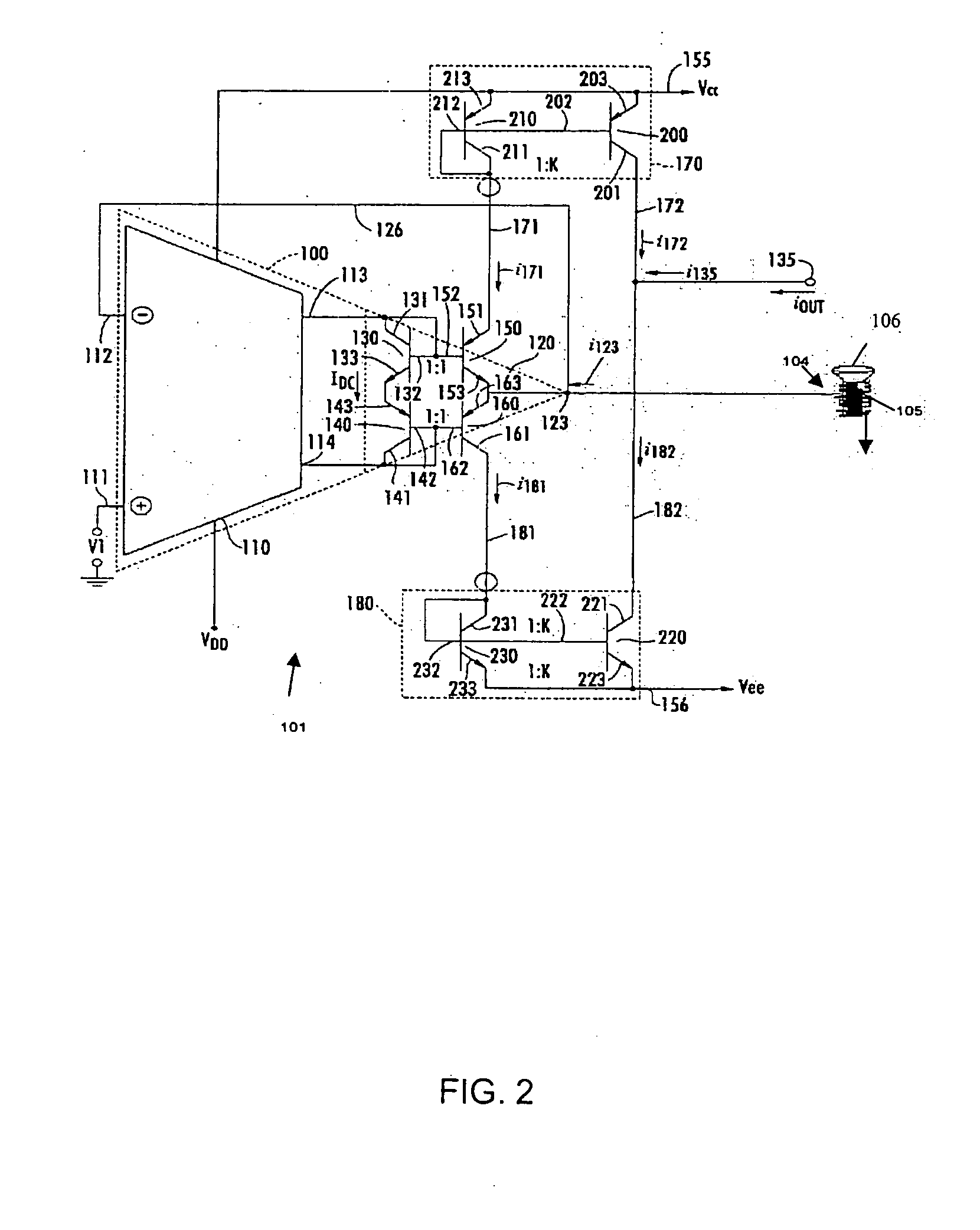
[0009] The amplifier virtually losslessly senses the speaker current as compared to conventional approaches which utilize inherently lossy sensing resistors. Series sensing resistors can substantially reduce the level of the signal to be manipulated for noise cancellation. As used herein, the phrase “virtually lossless sensing” refers to sensing the speaker current including thee back current noise signal without using a conventional series sensing resistor. In one embodiment, the amplifier can be a transconductance amplifier which senses the speaker current including the back current noise signal. The transconductance amplifier preferably uses a current mirror arrangement.
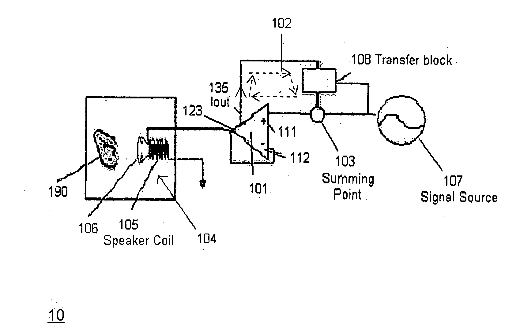
[0010] A feedback circuit receives the speaker current sensed and output by the amplifier and provides a feedback signal comprising a modified version of the noise signal to a summing point, wherein the feedback signal and the signal from the signal source are mixed. The summing point is coupled to an input of the amplifier. By adding the feedback signal in the correct anti-phase to the signal from the signal source, the noise in the vicinity of the ear / speaker is virtually eliminated.

Problems solved by technology

The amplifier virtually losslessly senses the speaker current as compared to conventional approaches which utilize inherently lossy sensing resistors.

Method used


Image

  • Noise cancellation using virtually lossless sensing method
  • Noise cancellation using virtually lossless sensing method
  • Noise cancellation using virtually lossless sensing method

Examples


Embodiment Construction

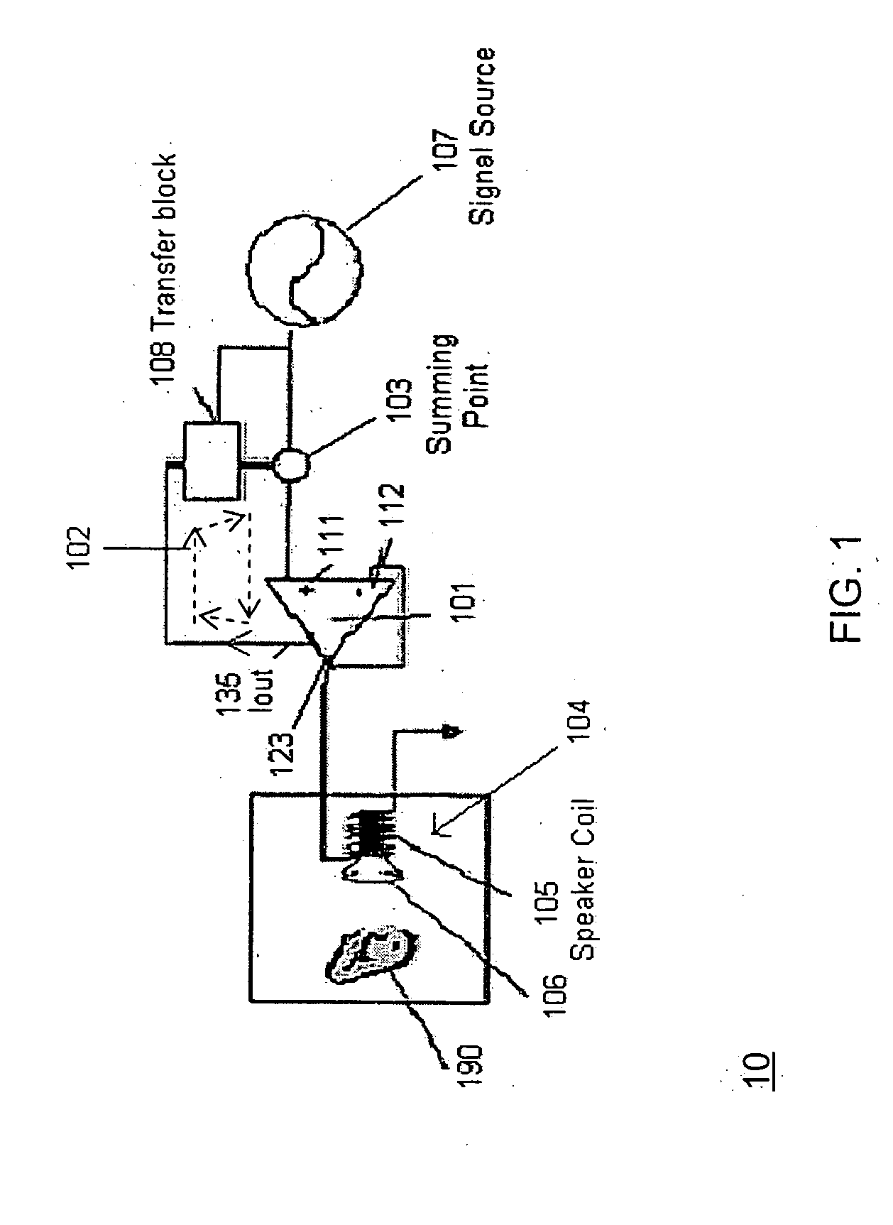
[0016] Referring to FIG. 1, an embodiment of the invention is shown. An active noise cancellation system 10 includes a signal amplifier 101 and a speaker 104, such as a headphone speaker, which is driven by the amplifier 101. The amplifier 161 includes inverting input 112, non-inverting input 111, output 123, and sensed current output (IOUT) 135. Although amplifier 101 is shown in FIG. 1 configured as a unity gain buffer, the invention is in no way limited to this arrangement.

[0017] Amplifier 101 also senses the ambient induced noise current (along with the signal source current) in the speaker coil 105. Speaker 104 includes a speaker coil 105, and speaker magnet (not shown) mounted on a diaphragm 106 for generating sound waves detectable by the ear of a listener 190. The speaker 104 is disposed proximate to the ear of the listener 190 so that the noise waves reaching the speaker 104 and sensed by coil 105 are virtually the same the noise waves reaching the ear of the listener 190....


PUM


Abstract

An active noise cancellation system includes at least one amplifier, and a speaker driven by the amplifier. The speaker comprises a speaker coil and a spaced apart speaker magnet mounted on a diaphragm. The speaker current in the speaker coil comprises a signal originating from a signal source and an ambient induced back current noise signal. The amplifier virtually losslessly senses the speaker current without the need for inherently lossy sensing resistors. A feedback circuit receives the speaker current sensed and output by the amplifier and provides a feedback signal comprising a modified version of the noise signal to a summing point, wherein the feedback signal and the signal from the signal source are mixed. The summing point is coupled to an input of the amplifier. By adding the feedback signal in the correct anti-phase to the signal from the signal source, the noise in the vicinity of the ear / speaker is virtually eliminated.

Description

CROSS-REFERENCE TO RELATED APPLICATIONS [0001] This application claims the benefit of Provisional Application No. 60 / 561,373, filed on Apr. 9, 2004, which is incorporated by reference in its entirety in the present application.STATEMENT REGARDING FEDERALLY SPONSORED RESEARCH OR DEVELOPMENT [0002] Not applicable. FIELD OF THE INVENTION [0003] The present invention relates to active noise cancellation systems, and more particularly, to headsets utilizing active noise cancellation. BACKGROUND OF THE INVENTION [0004] Conventionally, passive headsets and over-the-ear earplugs include a pair of earpieces coupled by a resilient headband. An annular foam pad attached to each earpiece forms a cushion between the shell of the earpiece and the user's head. The resilient headband presses the earpieces against the head of the user. Ambient sound is attenuated before it reaches the wearer's ear by occlusion of sound by the earpieces and absorption of transmitted sound by materials within the earp...

Claims


Application Information

Patent Timeline
IPC IPC(8): H04R3/00H04R29/00
CPCH04R3/002
Inventor LUDEMAN, CHRISTOPHER
Owner INTERSIL INC
Learn More