Continuous application of paint, via a traditional paint brush

Inactive Publication Date: 2005-10-13
LAWRENCE JOHN S
View PDF4 Cites 17 Cited by
  • Summary
  • Abstract
  • Description
  • Claims
  • Application Information

AI Technical Summary

Benefits of technology

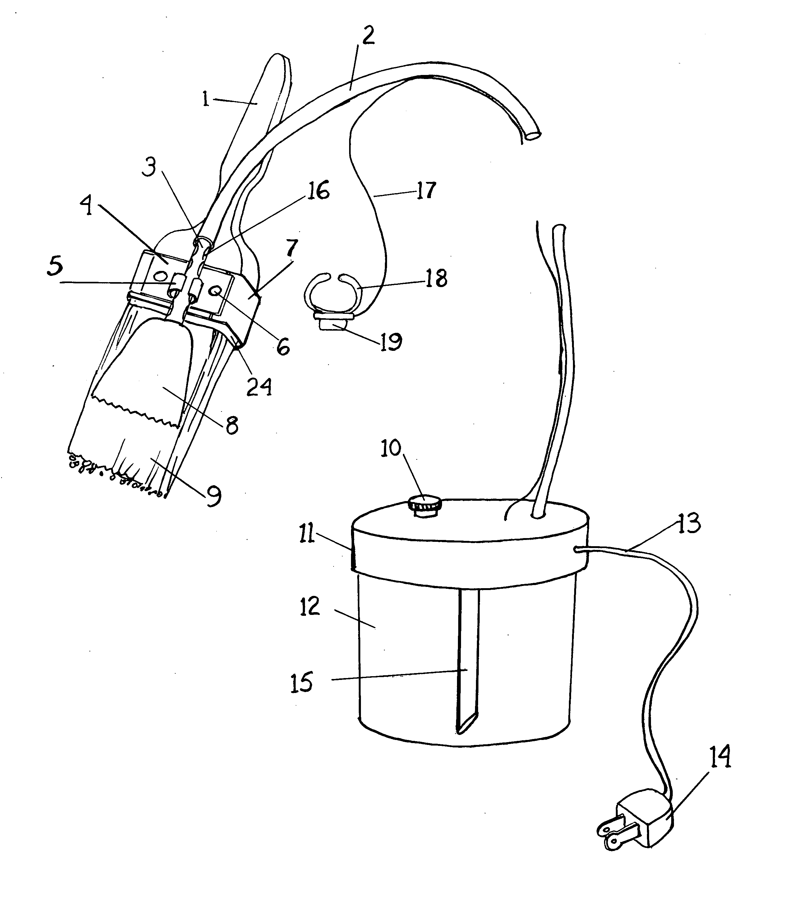
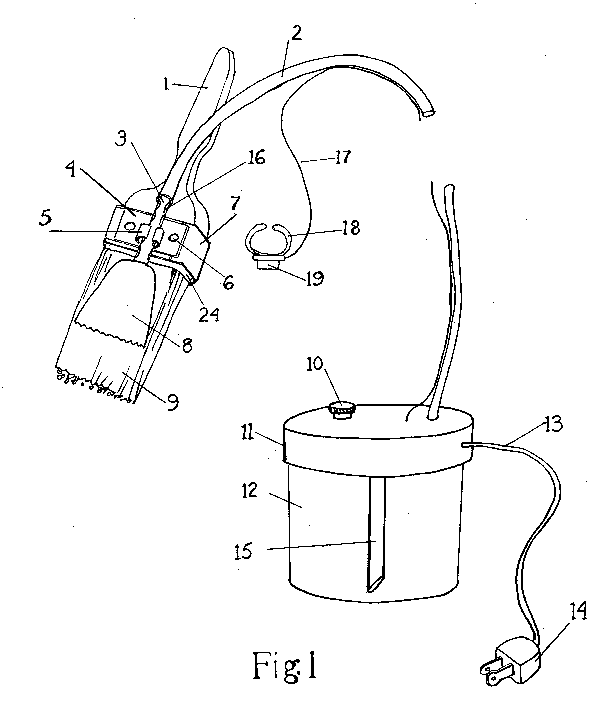
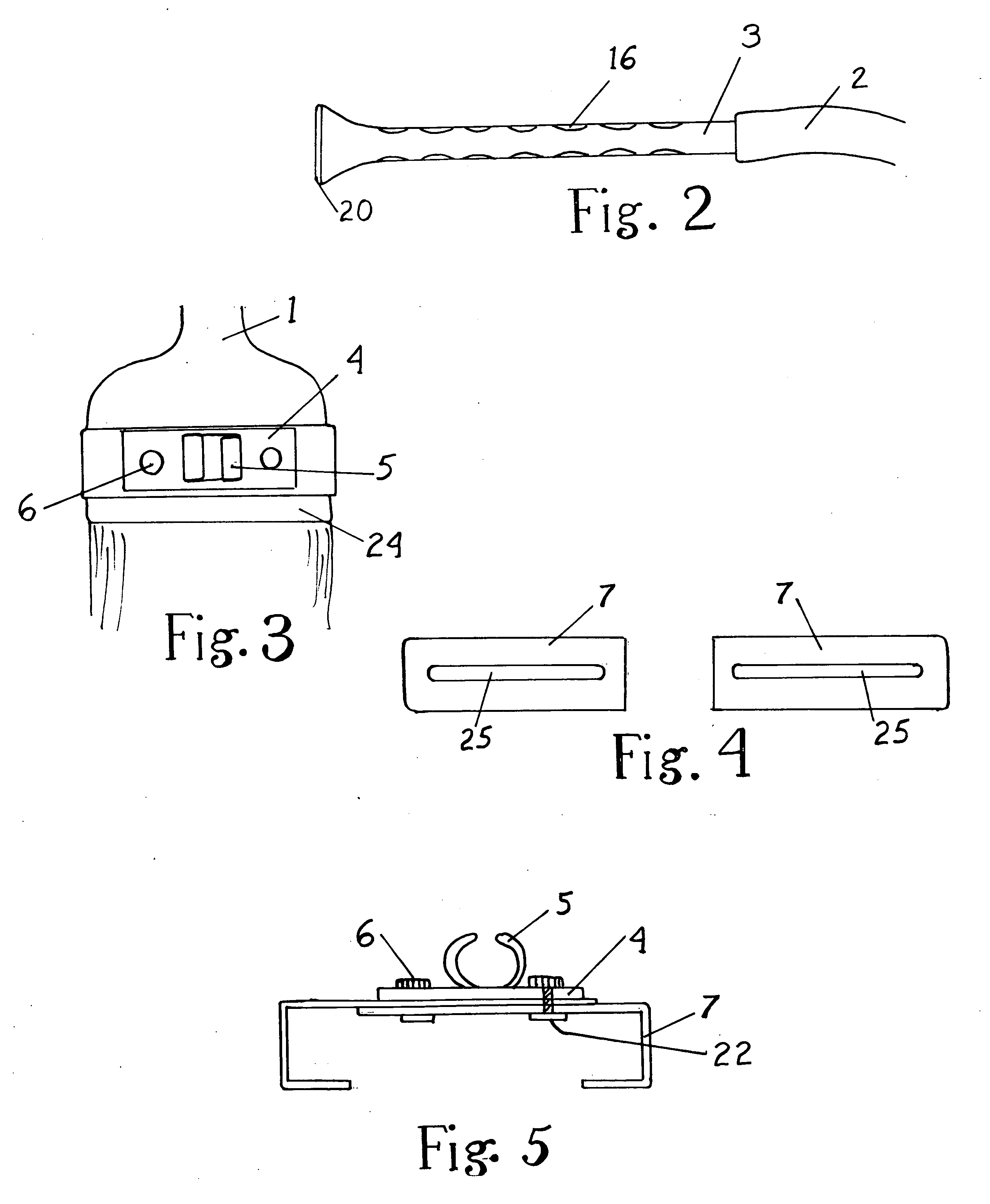
[0005] In the preferred embodiment, the invention consists of a number of interrelated members, that when joined together consist of a standard, off the shelf paint brush as is commonly found universally, consisting of a wooden or other material, handle, a metal or other material binding strap which secures the “brush” end, be it bristles, foam or other material to the handle, in addition a rigid, stationary platform of approximately two inches in length and one and one-quarter inches in width, which is placed and located on the “connecting strap” area of the paint brush. This stationary platform also features two internally threaded knobs at either end of the platform which can be turned on a screw, which projects from below the platform. This screw is an integral component of a disk-like boss at one end, the purpose of which is to pass through and engage a slot in two separate “J” shaped brush clamps, which are positioned below and contiguous to the stationary platform, the boss being below the brush clamp on each of the two sides. The purpose of the adjustable brush clamps is to provide the option of securing the device to brushes of differing widths, be it 2 inches, 2½ inches, four inches, etc. Additionally, the brush clamps could be conformed to retain a round-type brush such as a “sash tool”. When in use, the stationary platform is positioned onto the paint brush in the area of the “connecting strap” and the two brush clamps are firmly snugged against the sides of the brush, and then the two nuts on the top of the platform are tightened onto the projecting screw, the boss engaging the underside of the brush clamps, thus providing a secure, friction-type retention of the stationary platform to the brush itself, both from top to bottom and side to side. The purpose of securing the stationary platform to the paint brush in this manner is to provide a secure, stable surface for a rigid, removable tube, which is itself attached to the platform via a pair of centrally located, semi-circular retaining clips, these clips being an integral part of the stationary platform. The tube itself has a series of concentric depressions which interlock and engage the tube with the platform retaining clips. These “detents” in the tube allow the tube to be firmly positioned along the longitudinal axis of the brush at the operator's discretion. The aforesaid tube is of such construction that a length of some of the tube projects beyond the stationary platform onto the handle area of the brush and at its termination, acts as a receiving end for another flexible tube. This secondary flexible tube acts as a connector and paint transfer vehicle from its termination at one end of the rigid tube at the paint brush, continuous to and connecting to a vessel, which itself contains a volume of paint at some distance from the brush. The other termination of the rigid, removable tube features a flattened, ovoid aperture, the whole of which is triangular in appearance, when viewed from the top surface. The purpose of this aperture is to distribute a volume of paint, which itself has been delivered to this point from the distant paint vessel, via the flexible connecting tube to the opposite end of the rigid tube. The triangular-shaped aperture serves two distinct functions, i.e., that of restricting the flow of the paint, via the narrowed opening and also providing a wider, fan-like paint distribution pattern. Furthermore, the triangular-shaped terminus of the rigid, removable tube is positioned on the top surface of the “bristle” end of the paint brush in such a manner as to deliver a controlled volume of paint onto the bristles, foam, or other material of the brush. This paint volume is then allowed to penetrate into the brush surface, however, the position of the triangular-shaped terminus of the rigid tube in relation to the “bristles” in no way interferes with the flexing of the bristles nor their action of spreading the paint onto the to-be-painted surface. Furthermore, there is another fan-shaped structure or member also known as the “distribution apron”, that consists of a flat, triangular array of bristles, foam or other material, which is separately bound together and attached to an integral pair of semi-circular clips on its underside. These clips engage the rigid, removable tube in an area of the tube somewhat in between the triangular-shaped tube terminus and the tube's own attachment to the stationary platform clips. The purpose of this additional structure or member is twofold, that is, in one instance, this member acts as a “paint shield”, in preventing the paint which has been delivered to the brush surface via the rigid removable tube from dripping away from the brush, as the paint is thus confined between its structure or member and the brush surface itself, should the brush be turned over in the hand of the operator, and, more importantly, the structure of distribution apron, whether fabricated out of brush-like bristles, a triangular piece of foam or flexible plastic-like material, both having a series of fan-shaped ridges on its underside, acts to distribute the paint in a fan-like pattern over a larger width of the bristle area and closer to the working ends of the bristles. In addition, this structure or memb

Problems solved by technology

Also, it would be possible to deliver paint via a spray-atomizing type of nozzle to the brush tip, but this would

Method used


Image

  • Continuous application of paint, via a traditional paint brush
  • Continuous application of paint, via a traditional paint brush
  • Continuous application of paint, via a traditional paint brush

Examples


Embodiment Construction

[0017] As shown in FIG. 1, an illustrative embodiment of the device which allows a measured stream of paint to be channeled from a remote paint vessel to the working end of a traditional paint brush and being summarily attached to the brush, whose handle 1 forms the upper portion of the brush, allowing the operator to grasp the brush in the hand, this having attached bristles 9 or other material such as dense foam, etc., comprising the working end of the brush, the same attached to the handle and being retained onto the handle via a metallic or other material “connecting strap”24, thus exhibiting the well known form of a traditional paint brush in common use, to which has been attached a stationary platform 4, some 2 inches by 1 and one half inches in measurement, being approximate, which to its underside has attached left and right “J” shaped brush clamps 7, which they themselves having the ability to be adjusted or moved to accommodate the various widths of different sizes of stan...


PUM


Abstract

A device capable of delivering a continuous or intermittent amount of common paint or paint-like material to a surface to be painted utilizing a standard, off the shelf paint brush, the novel use of which allows the operator the ability to continuously paint with the brush and not having to break the work sequence of painting by continuous interruption of having to reload the brush by dipping it into a paint can, the component parts of which consists of a stationary platform which is centrally mounted on the brush in between the area of the brush handle and bristles, this being securely held in place by a pair of lateral brush clamps, these designed to accommodate a variety of brush sizes and widths, and or as an alternative, a broad band of flexible material having a series of central perforations, longitudinally and also having at its ends, reusable, self-adhesive material, and a rigid tube that is mounted on the top of the stationary platform or, alternately, held in place centrally by the perforations in the flexible banding, the tube acting as a conduit for paint, which is delivered from a remote source to the rigid tube via another flexible connecting tube, the paint being pumped or otherwise delivered to the rigid tube terminus and thus flowing onto the bristle portion of the brush, the paint flow being properly distributed on the bristles by an attached apron, which also aids in reducing paint drippings, all of which allows the painter to continuously apply paint to a surface without interruption or increased fatigue.

Description

BACKGROUND OF THE INVENTION [0001] The invention relates to the common paint brush and devices using bristle-type fibers or a foam core-type brush to apply paint to a surface, and, in particular to a device that allows any ordinary paint brush to have a stream of paint delivered to the bristle, foam, or other applicator end in an intermittent fashion, more or less paint, under the control of the operator at will. [0002] The application of paint or coloration of a surface, via a paint brush or brush-like device, in order to improve its appearance or preserve the underlying substrate, is a common procedure that is well known. Over the years, paint brushes, consisting of wood or other material used to construct a handle and having attached a series of bristles or bristle-like material, which have the ability to retain a volume of paint, when the said bristles are dipped into a paint can, are then used in a back and forth motion by the hand of the operator to apply paint onto a surface....

Claims


Application Information

Patent Timeline
IPC IPC(8): A46B1/00A46B11/00A46B11/06A47L13/22B05C17/00B44D3/12
CPCA46B11/0006A46B11/06B44D3/12B05C17/002A46B2200/202
Inventor LAWRENCE, JOHN S.
Owner LAWRENCE JOHN S
Why Eureka
Try Eureka