Pump, cooling apparatus, electrical appliance and personal computer combined with the pump

a technology of cooling apparatus and pump, which is applied in the field of pumps, can solve the problems of reducing the flow amount and speed of fluid, lowering the cooling performance, and thus the apparatus constructed, and achieves the effect of minimizing the pressure loss at the connection poin

Inactive Publication Date: 2005-10-13
KK TOSHIBA
View PDF5 Cites 18 Cited by
  • Summary
  • Abstract
  • Description
  • Claims
  • Application Information

AI Technical Summary

Benefits of technology

[0013] Upon combining with the pump a heat-receiving section placed in contact with the object to be cooled for removing the heat from the object to be cooled by the fluid flowing therein, and a heat-dissipating section including a fluid pipe having the end portions connected to the suction port and the discharge port and in which the fluid that has removed the heat from the object to be cooled flows, a cooling apparatus can be achieved.
[0014] With such a configuration, since the suction port and the discharge port are extended in different directions, the end portions of the fluid pipe no longer have to be bent in an acute angle for connection with the suction port and the discharge port. Consequently, a pressure loss at the connection point can be minimized.

Problems solved by technology

However, the cooling apparatus thus constructed has the following drawback.
Such a structure increases the pressure loss inside the pipe 14 and hence reduces a flow amount and speed of the fluid, thereby resulting in lowering the cooling performance.

Method used


Image

  • Pump, cooling apparatus, electrical appliance and personal computer combined with the pump
  • Pump, cooling apparatus, electrical appliance and personal computer combined with the pump
  • Pump, cooling apparatus, electrical appliance and personal computer combined with the pump

Examples


first embodiment

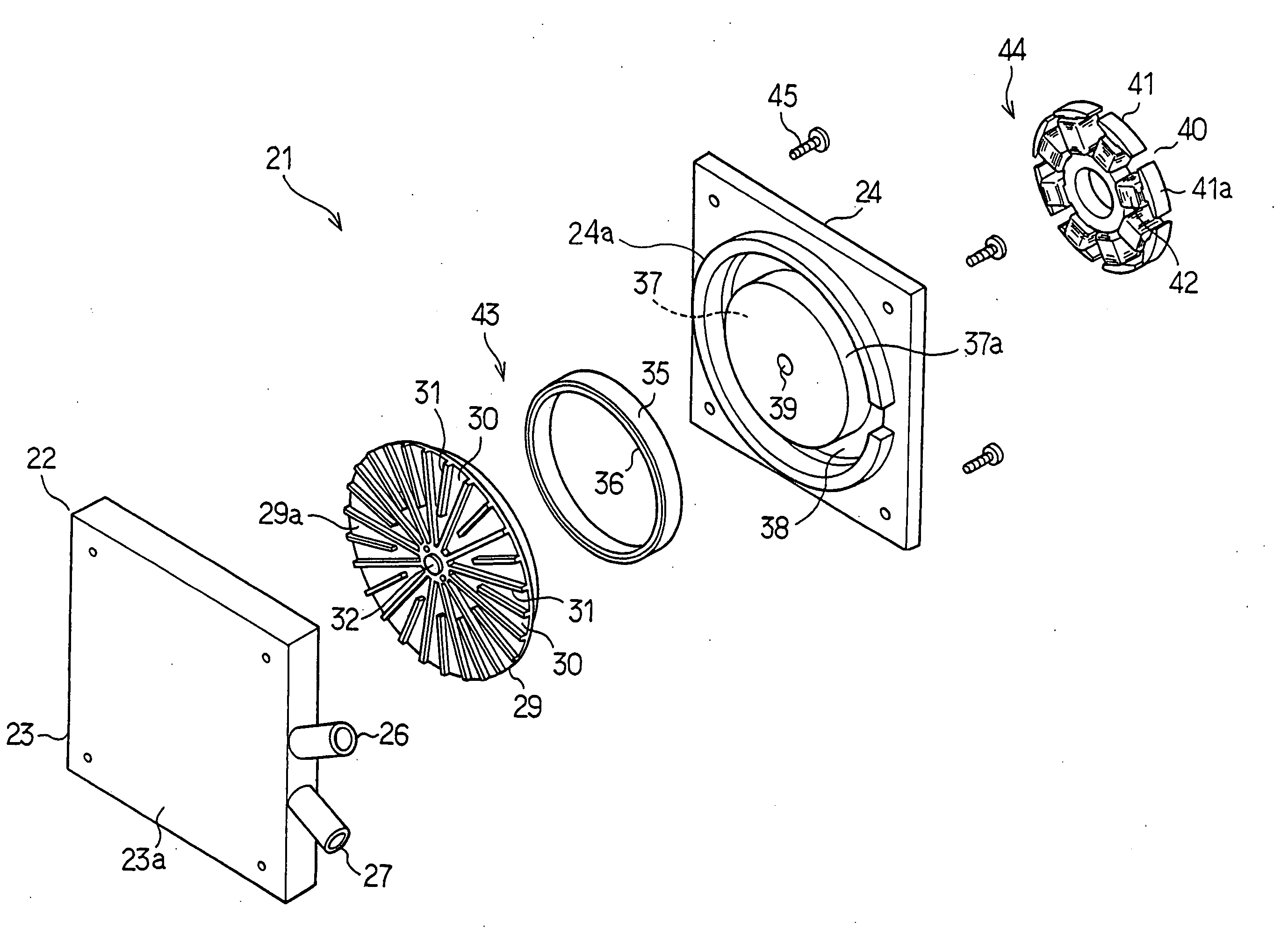
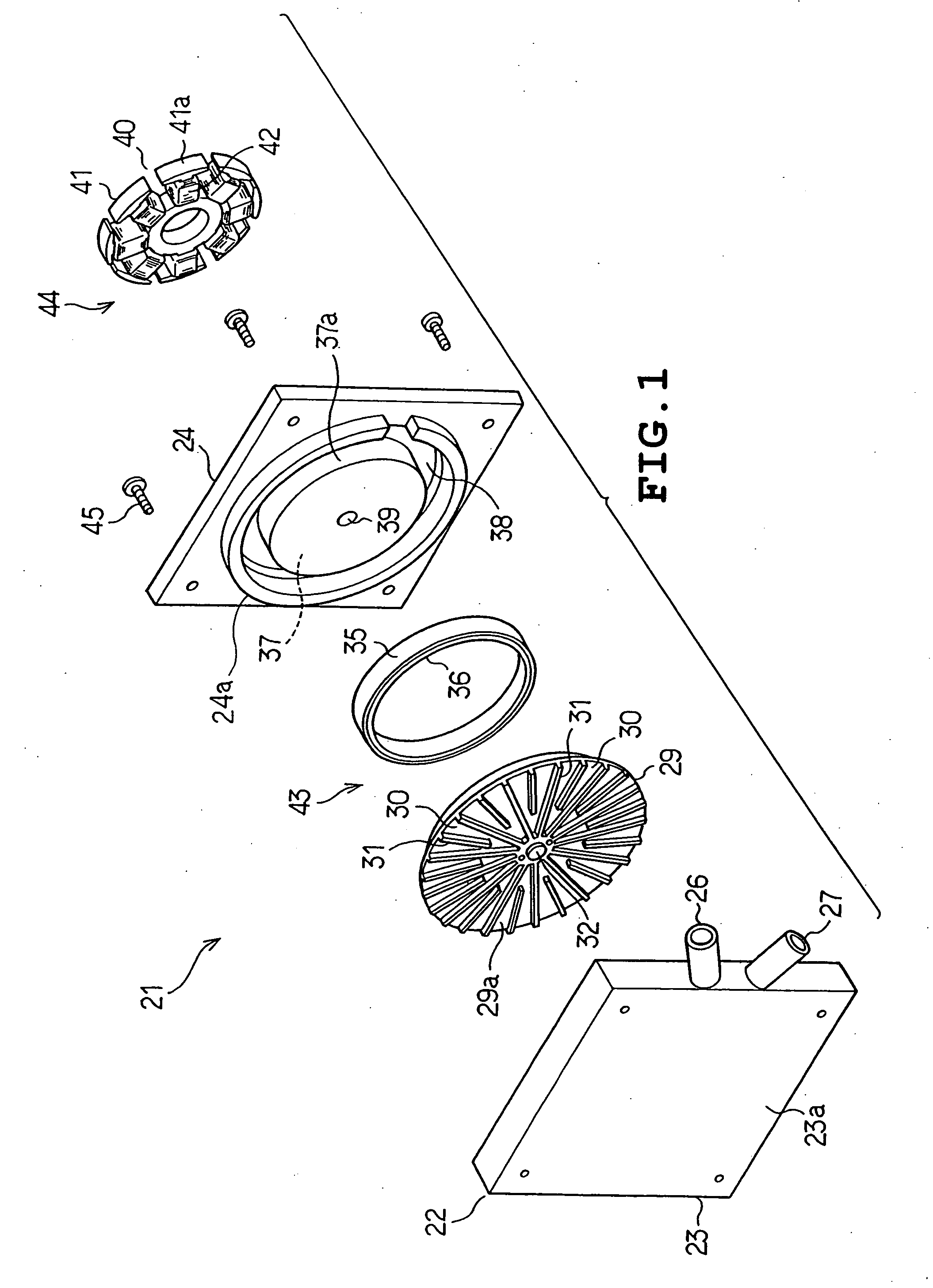
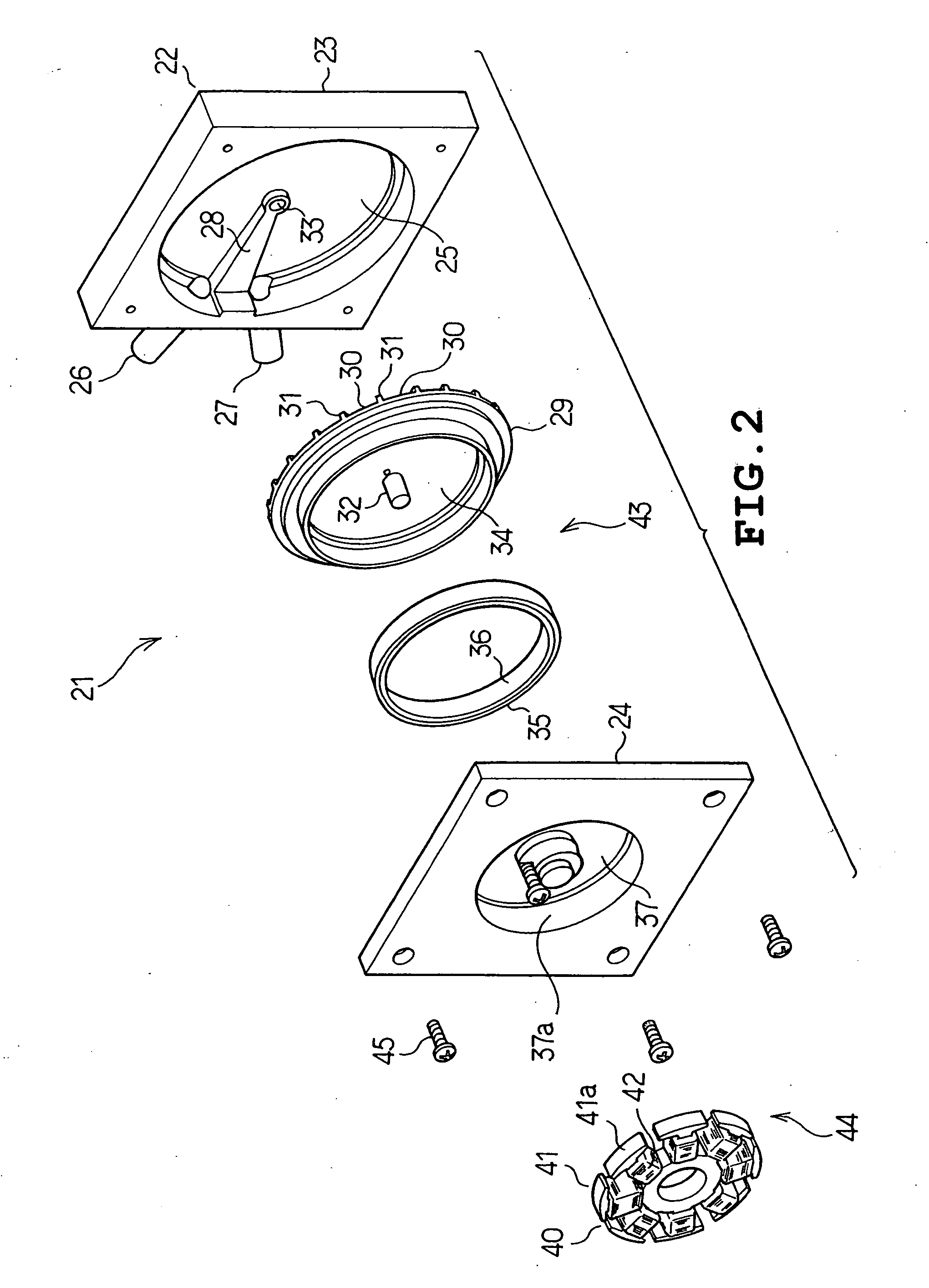
[0028] Referring to the accompanying drawings, some embodiments of the present invention will be described hereunder. FIG. 1 through FIG. 5 depict the present invention, among which FIGS. 1 to 3 illustrate a fluid pump according to this embodiment, while FIGS. 4 and 5 show a configuration of a cooling apparatus with which the fluid pump is employed. As shown in FIGS. 1 to 3, the fluid pump 21 includes a casing 22 constituted of a rectangular plate-shaped casing body 23 and a casing cover 24.

[0029] The casing body 23 includes a pump chamber 25 having a circular recessed portion, and a suction port 26 and a discharge port 27 communicating with the pump chamber 25. Both the suction port 26 and the discharge port 27 are projecting outward from a same sidewall of the casing body 23, but in different directions. More specifically, the suction port 26 is oriented in a diagonally upward direction, while the discharge port 27 is oriented in a diagonally downward direction in FIG. 1. The face...

third embodiment

[0053] shown in FIG. 7, a cooling apparatus 81 includes the pump 21 having a pair of each of the suction ports 26 and the discharge ports 27, and a pair of heat-dissipating sections 52 respectively connected to the suction ports 26 and the discharge ports 27. The pump 21 of this embodiment integrally includes a heat-receiving section.

[0054] In this embodiment, either of the suction port 26 or the discharge port 27 out of a pair disposed side by side from a same outer face of the pump 21 is perpendicularly oriented with respect to the outer face of the pump 21, while the other is inclined with respect thereto.

fourth embodiment

[0055] According to the present invention shown in FIG. 8, a cooling apparatus 91 includes the pump 21 having a pair each of the suction ports 26 and the discharge ports 27, and a pair of heat-dissipating sections 52 respectively connected to the suction port 26 and the discharge port 27, and a pair of heat-receiving sections 72 connected between the respective discharge ports 27 and the heat-dissipating sections 52. In this embodiment too, either of the suction port 26 or the discharge port 27 out of a pair disposed side by side from a same outer face of the pump 21 is perpendicularly oriented with respect to the outer face of the pump 21, while the other is inclined with respect thereto.


PUM


Abstract

A pump according to the present invention includes a casing including a pump chamber through which a fluid flows, an impeller rotatably mounted inside the pump chamber, a suction port mounted on the casing for suctioning the fluid into the pump chamber by the rotation of the impeller; and a discharge port mounted on the casing for discharging the fluid out of the pump chamber by the rotation of the impeller, and the suction port and the discharge port are oriented so as to extend in different directions.

Description

BACKGROUND OF THE INVENTION [0001] 1. Field of the Invention [0002] The present invention relates to a pump for cooling a heat-generating component in an electrical appliance or a personal computer, and more particularly to a pump with an improved structure of a suction port and a discharge port. [0003] 2. Description of the Related Art [0004] A fluid pump as disclosed, for example, in Japanese Published Unexamined Patent Application No. 2001-123978 and Japanese Published Unexamined Patent Application No. 2001-132677 is currently available. Such a fluid pump is provided with a casing including therein apump chamber, a suction port and a discharge port located in the casing, and a disc-shaped impeller rotatably mounted inside the pump chamber and having pump grooves along a periphery thereof for carrying a liquid inside the pump chamber. In this fluid pump, when the impeller is rotated the pump grooves act to suction the liquid through the suction port into the pump chamber, and also...

Claims


Application Information

Patent Timeline
Patent Type & Authority Applications(United States)
IPC IPC(8): F04D29/44F04B17/00F04B17/03F04B35/00F04B35/04F04D5/00F25D9/00G06F1/20H01L23/473H05K7/20
CPCF04D5/002G06F1/203F04D29/582
Inventor SEKO, KATSUYAITO, KENICHIHASEGAWA, YUKIHISAOKADA, KYOUICHINAKAYAMA, TADAHIRO
Owner KK TOSHIBA
Why Eureka
Try Eureka