
Flow control method in a telecommunications system

a technology of telecommunications system and flow control method, which is applied in the direction of digital transmission, data switching network, network traffic/resource management, etc., can solve the problems of end-to-end connection related flow control not being supported by current atm specifications, deteriorating data integrity, and end-to-end flow control failing, etc., to achieve flexible and simple

Inactive Publication Date: 2005-10-13
NOKIA SOLUTIONS & NETWORKS OY
View PDF7 Cites 35 Cited by
  • Summary
  • Abstract
  • Description
  • Claims
  • Application Information

AI Technical Summary

Benefits of technology

[0028] In order to implement the flow control, the flow control information may be employed by the user layer protocol entity. The user layer entity may implement the above flow control by controlling the data input from the user layer to the underlying lower transmission protocol layer, and / or by activating the flow control mechanism of the lower transmission protocol layer of the previous leg in the uplink direction, e.g. by mapping or converting the tunnelled flow control information into the flow control information according to the protocol of the next leg. In the latter case the lower layer protocol entity of the previous leg in the same node may stop forwarding new data to a leg not supporting the flow control, and / or the respective lower protocol entity at the far end of the previous leg may stop sending new data. In each case the data flow on the lower transmission protocol level of the leg not supporting the flow control can be controlled and the overflow of data buffers or discarding of data can be avoided in each leg of the end-to-end connection. As a result, the integrity of the data can be assured with the lower level flow control mechanisms only, without any need for high-level flow control. Also large buffers will be avoided. The inventive concept also allows, however, the use of a high-level protocol, such as the LAC, in one of the legs of the connection or over the whole end-to-end connection.
[0030] In the preferred embodiment of the invention the connection leg not supporting the flow control is an ATM connection, and the lower transmission protocol level includes an ATM adaptation layer. In order to implement the in-channel signalling embodiment, flow control information may be inserted into the ATM adaptation layer service data unit which is then transported over the leg not supporting the flow control to the other end in accordance with an ATM network protocol. At the other end the flow control information is extracted from the ATM adaptation layer service data unit. In the preferred embodiment of the invention, the flow control information is inserted into the user data field of the ATM adaptation layer service data unit. The in-channel signalling approach is a very flexible and simple way to arrange the tunnelling of the flow control information. In the out-channel signalling approach, some modification in the signalling messages may be required, depending on the signalling system used.

Problems solved by technology

Moreover, in case of concatenated legs, the transmitting end may also activate the flow control in the previous leg in order to avoid the filling up of the receiving buffer since it is not able to forward the received data in the ‘active flow control’ mode.
However, no end-to-end connection related flow control is supported by the current ATM specifications.
The discarding of data will deteriorate the data integrity.
The fact that the end-to-end flow control is not supported by the ATM results in problems when the ATM is used in the interface lu between the RNC and the 3GMSC or the IWU, as shown in FIGS. 2 and 3.
More particularly, one leg along the end-to-end connection consisting of various concatenated legs does not support flow control, and therefore the end-to-end flow control fails.
In case there is no LAC over any of the legs or the LAC is operating between the MS and the RNC only, the current flow control mechanisms cannot guarantee data integrity in a circuit switched data call in the 3G mobile network using the ATM connection between the RNC and the MSC (or the IWU).
The flow control towards the ATM leg does not stop sending data from the sending entity but leads to an overflow of the receiving buffer or to discarding of ATM cells carrying user data.
In the latter case the use of the huge buffer in order to maintain the integrity of the data is very impractical due to the memory requirements in the RNC.
In any case this will not work at all if there is no LAC at all or the LAC operates only between the MS and the RNC.
A similar problem may be encountered in any telecommunications system in which one or more of the concatenated connection legs do not support flow control.

Method used


Image

  • Flow control method in a telecommunications system
  • Flow control method in a telecommunications system

Examples


Embodiment Construction

[0035] The preferred embodiments of the invention are described in the following as implemented in the third generation mobile system when the transport network is an ATM network. However, the aim is not to restrict the invention to these embodiments. The invention is applicable to be used in any telecommunications system in which an intermediate connection leg fails to support any lower level flow control mechanism while such a flow control mechanism is supported by the connection legs or equipment to which the intermediate leg is connected to. As used herein, the term leg may also refer to a user interface between a node and user equipment or application connected thereto.

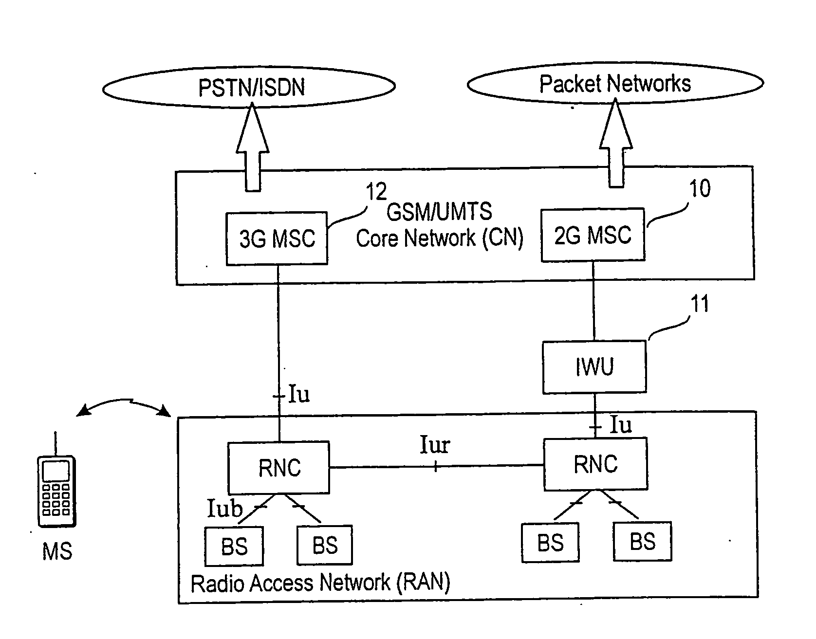
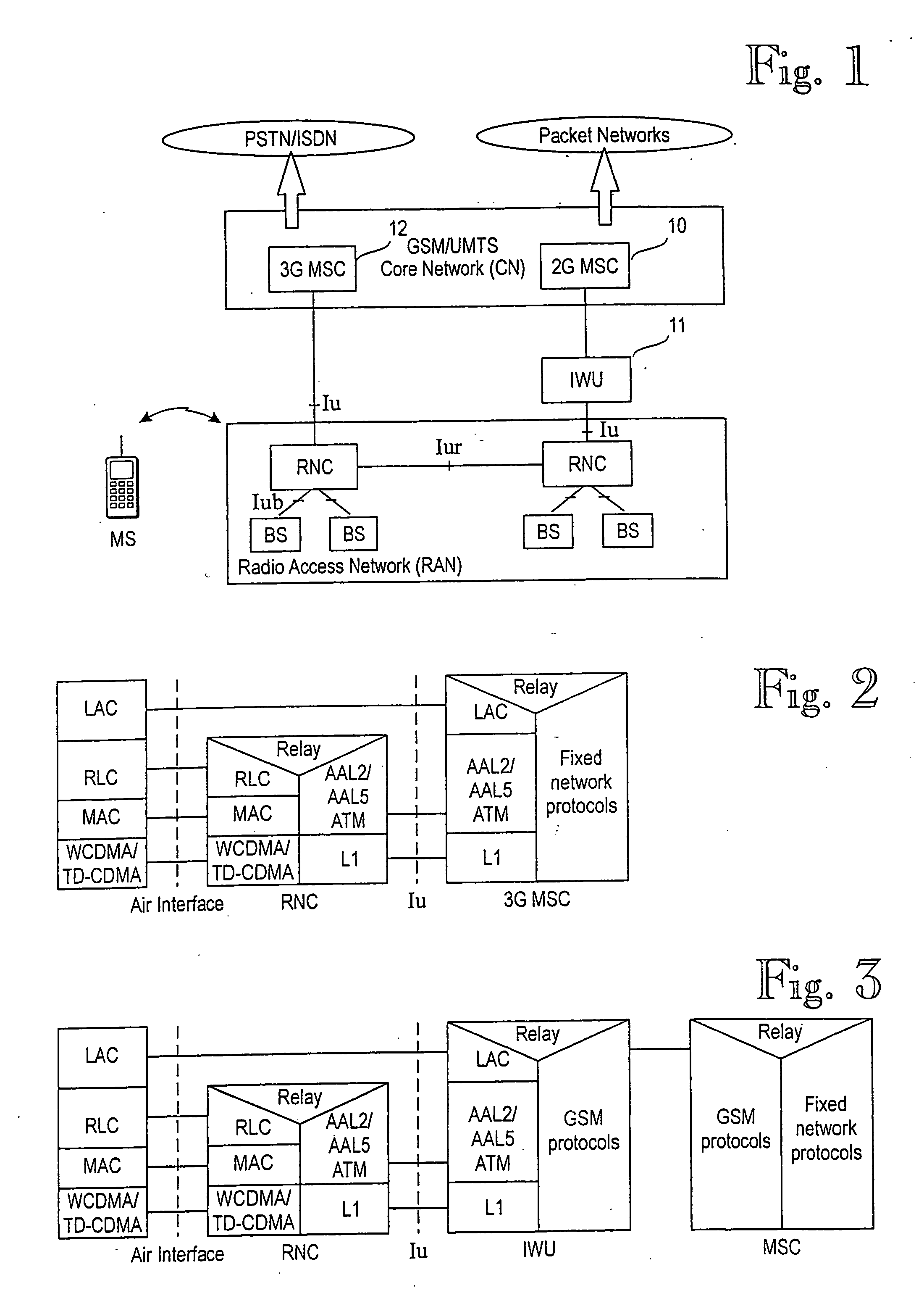
[0036] The architecture of the UMTS access network was described above with reference to FIG. 1, and examples of the protocol stacks were illustrated in FIGS. 2 and 3.

[0037] With reference to FIGS. 2 and 3, the relay layer in the RNC and in the 3GMSC or the IWU illustrates any high-layer protocols or entities r...


PUM


Abstract

The invention relates to flow control in data transmission in telecommunications systems, particularly in wireless telecommunications systems. In the present invention flow control information is tunnelled over a connection leg which does not support flow control on a lower transmission protocol layer underlying a user level. The nodes at the both ends of the leg are arranged to use the flow control information to control the data flow on the lower transmission protocol level of the leg. In other words, the transmission of new data on the lower transmission protocol level is ceased or the data rate decreased when the flow control information activates the flow control in the transmitting node, and similarly, the transmission of new data on the lower transmission protocol level is restarted or the data rate increased when the conveyed flow control information deactivates the flow control.

Description

[0001] This is a continuation of U.S. patent application Ser. No. 09 / 869,069, filed Jun. 22, 2001, which is the U.S. National Stage of International Application No. PCT / FI00 / 00025, filed Jan. 14, 2000, which relies for priority upon Finnish Patent Application No. 990071, filed Jan. 15, 1999, the contents of all of which are incorporated herein by reference in their entireties.FIELD OF THE INVENTION [0002] The invention relates to flow control in data transmission in telecommunications systems, particularly in wireless telecommunications systems. BACKGROUND OF THE INVENTION [0003] Wireless communications systems refer generally to any telecommunications system which enables wireless communication between the users and the network. In mobile communications systems users are capable of moving within the service area of the system. A typical mobile communications system is a public land mobile network (PLMN). [0004] The present third generation mobile systems, such as Universal Mobile C...

Claims


Application Information

Patent Timeline
IPC IPC(8): H04L12/54H04W28/10
CPCH04L12/5602H04L2012/5607H04W28/10H04L2012/5665H04L2012/5635
Inventor RASANEN, JUHAOHVO, MIKKO
Owner NOKIA SOLUTIONS & NETWORKS OY
Learn More