Hydraulic tensioner

a hydraulic tensioner and tensioner technology, applied in the direction of belts/chains/gearings, mechanical equipment, belts/chains/gearings, etc., can solve the problems of high machining accuracy, limited width of hydraulic tensioner protrusions, and difficult assembly of hydraulic tensioner incorporating the conventional check valve mechanism, so as to avoid wear and contact noise

Active Publication Date: 2005-10-13
TSUBAKIMOTO CHAIN CO
View PDF22 Cites 37 Cited by
  • Summary
  • Abstract
  • Description
  • Claims
  • Application Information

AI Technical Summary

Benefits of technology

[0012] The hydraulic tensioner of the invention maintains proper tension in a chain, a belt, or other traveling flexible power transmission medium in the same manner as a conventional hydraulic tensioner. However the tensioner exhibits a number of significant advantages over the conventional tensioner.
[0013] The disc-shaped retainer is fixed to the ball guide by crimping the ball guide over an annular region that extends substantially entirely around the periphery of the retainer. Accordingly, in contrast with the tensioner shown in FIGS. 6 and 7, in the tensioner according to the invention, the crimped portion of the ball guide provides for a stronger check valve unit, and allows the check valve unit to be assembled without careful positioning of the retainer relative to the ball guide. Furthermore, because the retainer is more securely attached to the ball guide, the check valve unit can be incorporated into the bottom portion of the plung

Problems solved by technology

High machining accuracy is required for production of the conventional check valve mechanism, and assembly of a hydraulic tensioner incorporating the conventional check valve

Method used


Image

  • Hydraulic tensioner
  • Hydraulic tensioner
  • Hydraulic tensioner

Examples


Embodiment Construction

[0023] The ball guide of the check valve unit may be composed of a synthetic resin or metal. However, it is preferably composed of synthetic resin so that crimping can be carried out by the application of heat, and assembly of the check valve unit can be carried out quickly and easily.

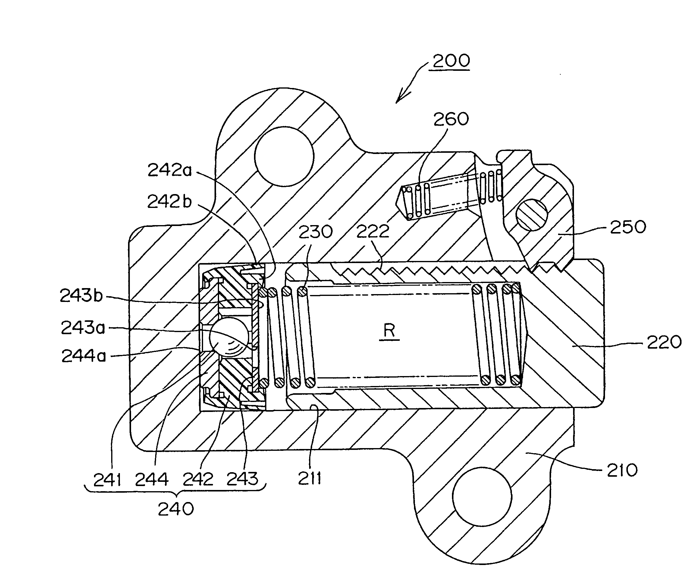
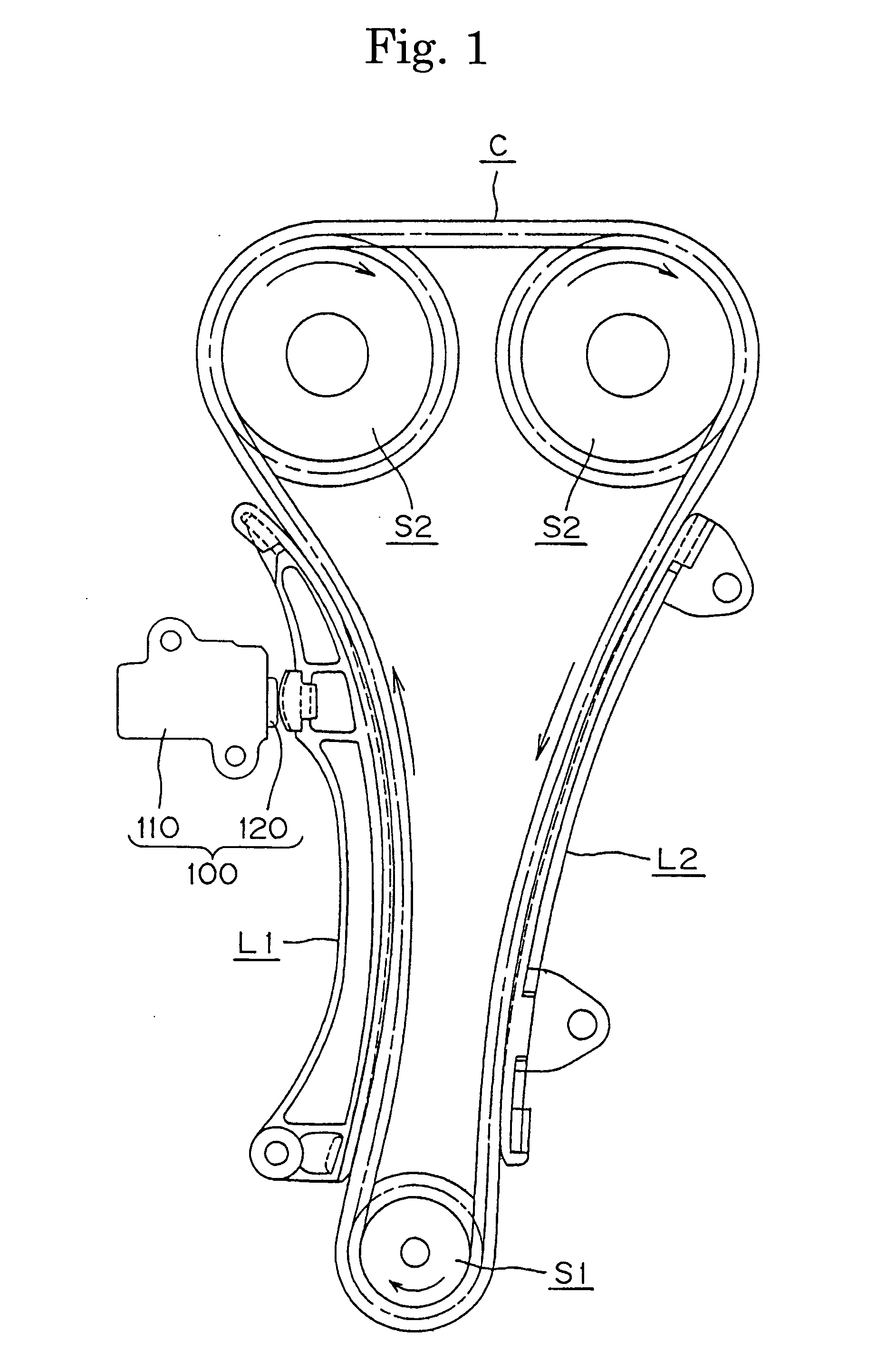
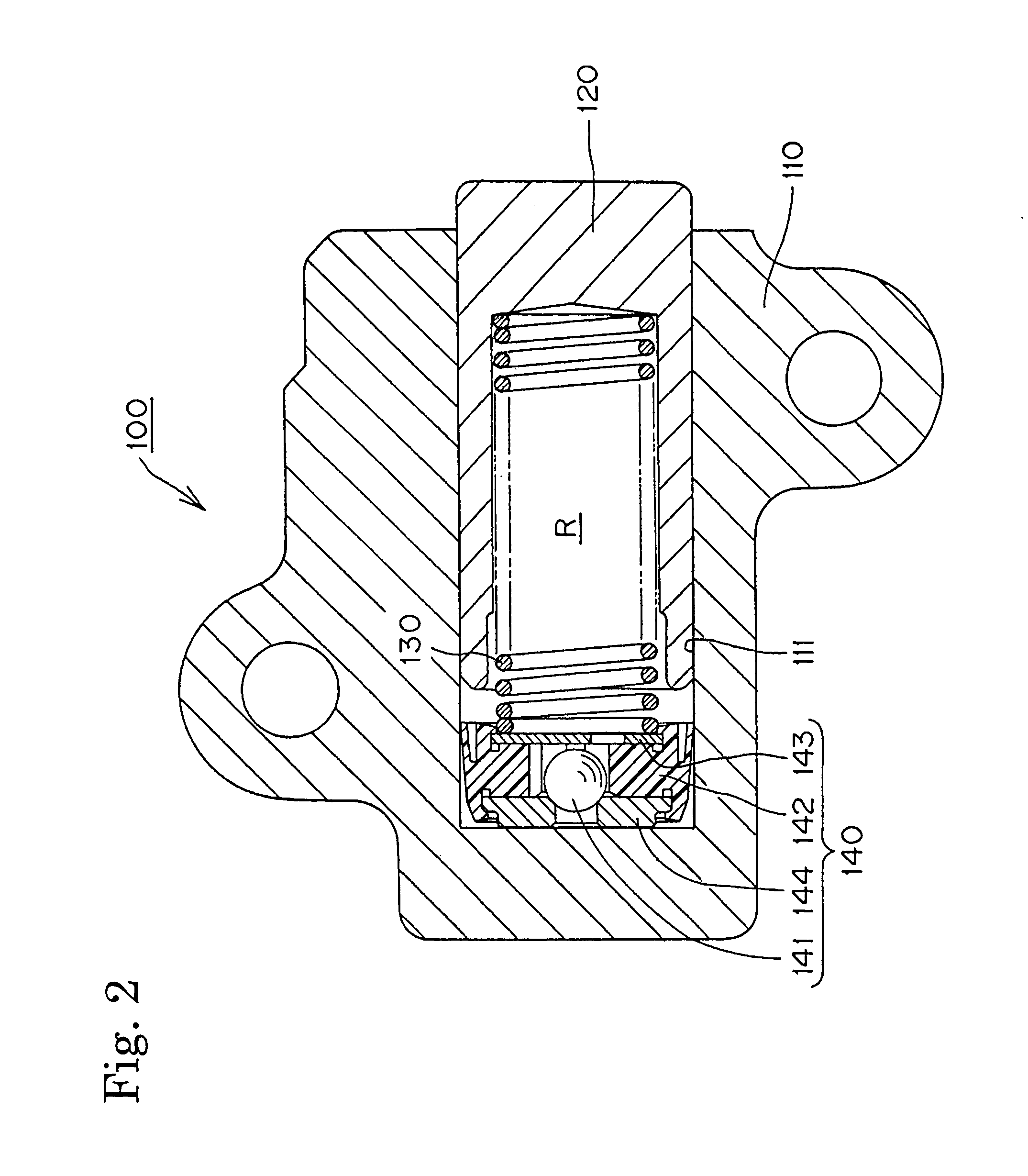
[0024] As shown in FIGS. 1 and 2, a hydraulic tensioner 100, in accordance with a first embodiment of the invention, is attached to an engine block adjacent the slack side of a timing chain C, which is in mesh with a drive sprocket S1 rotated by a crankshaft of an engine and driven sprockets S2 on valve-operating camshafts. A plunger 120 protrudes through an opening of a cylindrical plunger-accommodating hole 111 in tensioner housing 110, and applies tension to the slack side of the chain C through a pivoted lever L1 by pressing against a back surface of the lever at a location remote from the lever's pivot axis. A fixed guide L2 guides the travel of the timing chain C on the tension side thereof. Arr...


PUM


Abstract

The check valve unit of a hydraulic tensioner comprises a check ball, a ball guide and a disc-shaped retainer. The retainer is fixed to the high pressure oil chamber side of the ball guide by crimping an annular portion of the ball guide over the outer edge of the retainer so that substantially all of an annular circumferential portion of the high pressure chamber side of the retainer is held underneath the crimped portion of the ball guide. The crimped portion of the ball guide forms a recess for receiving and positioning a plunger-biasing spring. A ball seat is similarly secured to the inflow side of the ball guide by crimping.

Description

FIELD OF THE INVENTION [0001] This invention relates to hydraulic tensioners of the type used to apply proper tension to the timing chain or timing belt of an internal combustion engine, and relates more particularly to improvements in the check valve of a hydraulic tensioner. BACKGROUND OF THE INVENTION [0002] Hydraulic tensioners have been widely used to maintain tension in timing chains and timing belts which transmit rotation from the crankshaft to one or more camshafts of a vehicle engine. By maintaining proper tension, the tensioner prevents vibration of the chain or belt. [0003] A conventional hydraulic tensioner includes a housing having a cylindrical hole, a plunger slidable in the cylindrical hole and protruding from an opening at the end thereof, and a plunger-biasing spring urging the plunger in the protruding direction. The housing and the plunger together form a high pressure oil chamber, and a check valve mechanism, comprising a metal cylinder, is fitted into the cyli...

Claims


Application Information

Patent Timeline
IPC IPC(8): F16H7/08F16H7/22
CPCF16H7/0848F16H2007/0806F16H2007/0859F16H2007/0853F16H2007/0812
Inventor YOSHIDA, OSAMU
Owner TSUBAKIMOTO CHAIN CO
Why Eureka
Try Eureka