Gravity referenced endoscopic image orientation

Active Publication Date: 2005-10-13
KARL STORZ IMAGING INC
View PDF8 Cites 53 Cited by
  • Summary
  • Abstract
  • Description
  • Claims
  • Application Information

AI Technical Summary

Benefits of technology

[0016] In an endoscope having a longitudinal axis, a view vector angularly offset from said longitudinal axis, an accelerometer, and an image rotator effectively responsive t

Problems solved by technology

This often results in rotation of the viewed image.
This is the very problem.
However, the surgeon is standing up, and the rotating image can be confusing to him.
None of the abov

Method used


Image

  • Gravity referenced endoscopic image orientation
  • Gravity referenced endoscopic image orientation
  • Gravity referenced endoscopic image orientation

Examples


Embodiment Construction

[0019] The following detailed description illustrates the invention by way of example, not by way of limitation of the principles of the invention. This description will clearly enable one skilled in the art to make and use the invention, and describes several embodiments, adaptations, variations, alternatives and uses of the invention, including what we presently believe is the best mode of carrying out the invention.

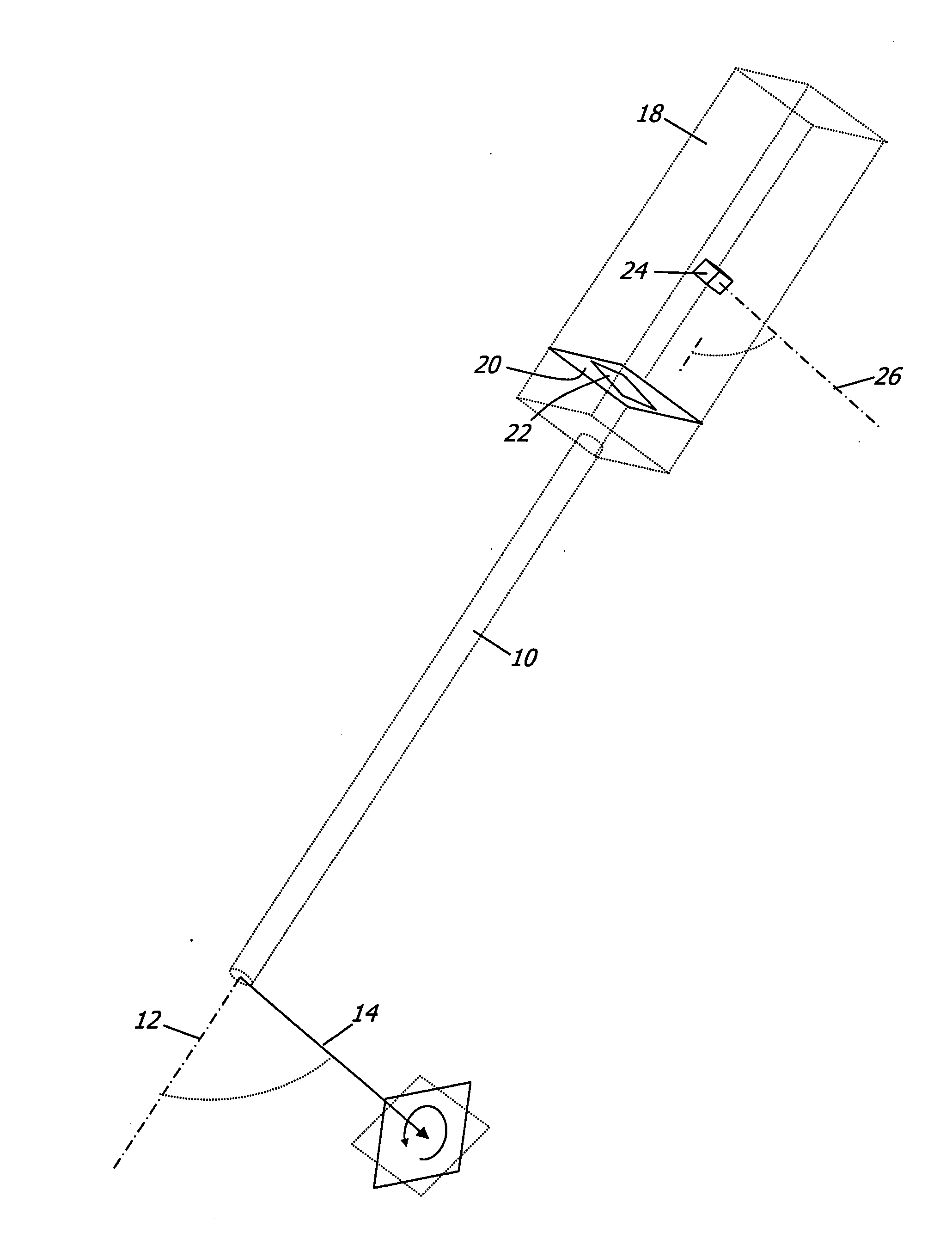
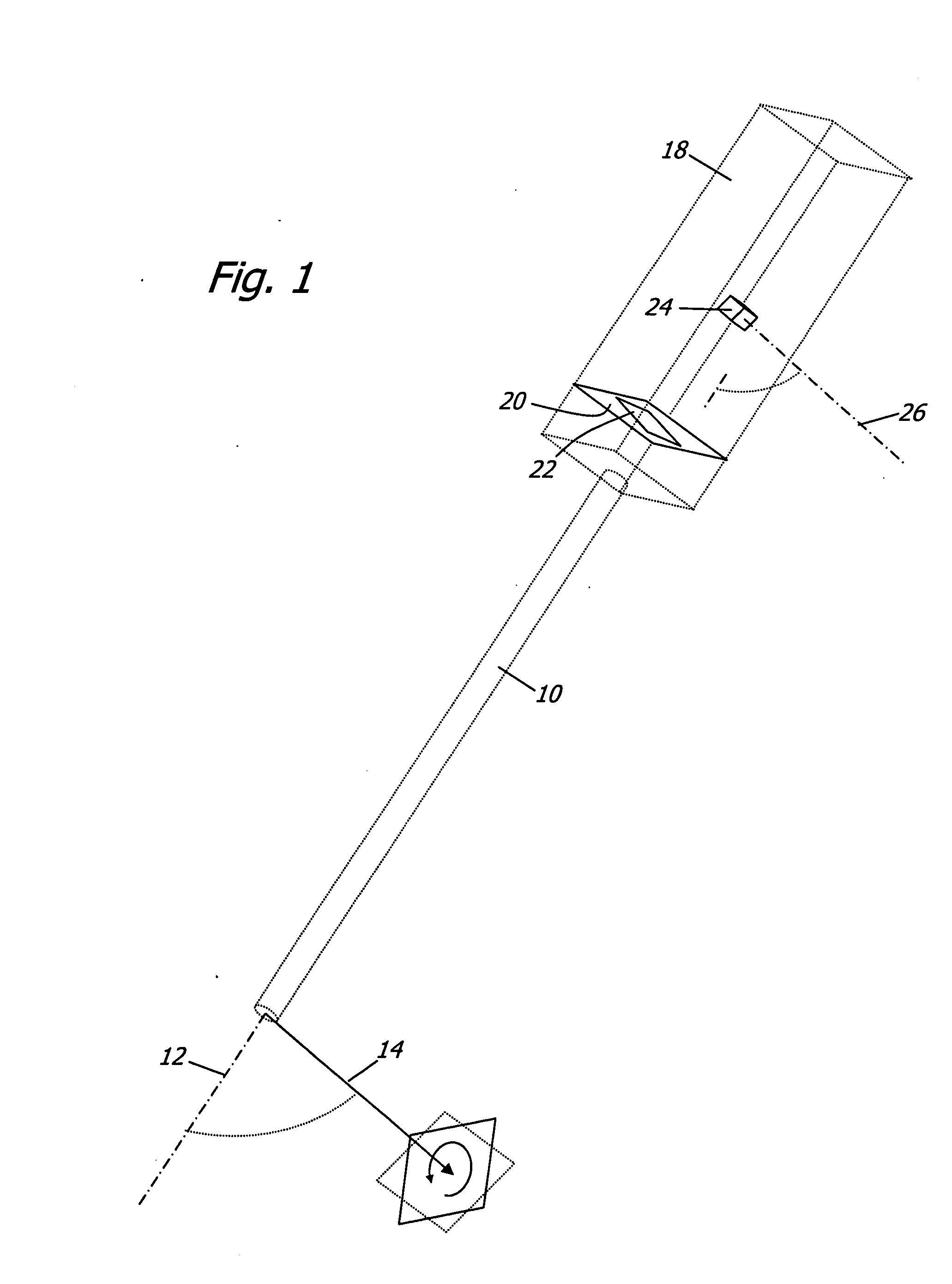
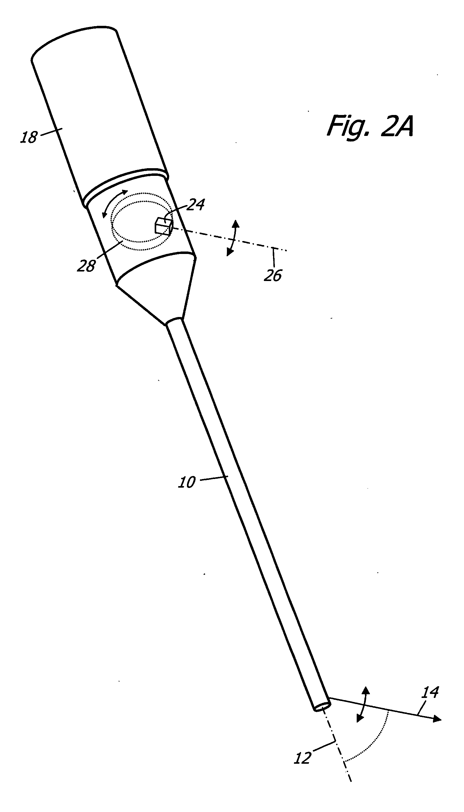
[0020]FIG. 1 shows a first embodiment of the invention. The endoscope includes a shaft 10 that contains elements that are conventionally provided. The shaft has a longitudinal axis 12. An objective optical system is provided at the distal end of the shaft to give the endoscope a view vector 14 that is angularly offset from the longitudinal axis 12. The objective optical system comprises components such as lenses, prisms, reflectors, etc.

[0021] A housing 18 is provided at the proximal end of the shaft 10. An image sensing device or camera 20 is mounted in the housing ...


PUM


Abstract

An endoscope having a longitudinal axis, a view vector angularly offset from said longitudinal axis, an accelerometer, and an image rotator effectively responsive to said accelerometer, wherein said accelerometer is arranged for measuring rotations about a measurement axis which is generally parallel to said view vector. Through the use of this apparatus, an image is maintained in an upright orientation.

Description

CROSS-REFERENCE TO RELATED APPLICATIONS [0001] This application claims the benefit of U.S. provisional application Ser. No. 60 / 560172 filed on Apr. 7, 2004, entitled “Gravity referenced endoscopic image orientation”, the contents of which are incorporated herein by reference.STATEMENT REGARDING FEDERALLY SPONSORED RESEARCH [0002] Not Applicable FIELD OF THE INVENTION [0003] The present invention relates to endoscopes (including devices such as borescopes, fiberscopes, etc.) in which the rotational orientation of the endoscopic image is presented in its actual relationship to the viewer's reference frame. BACKGROUND OF THE INVENTION [0004] Many endoscopes view only directly forward. Others feature fixed or movable reflectors in the distal portion to allow off-axis viewing. Some, most commonly flexible types, feature actuated bending portions at the distal end. This invention is applicable to all types of axial, non-axial, and variable direction of view endoscopes. [0005] Today, typic...

Claims


Application Information

Patent Timeline
IPC IPC(8): A61B1/04
CPCA61B1/00045A61B1/042A61B2562/0219
Inventor SCHARA, NATHAN JONHOEG, HANS DAVIDHALE, ERIC LAWRENCE
Owner KARL STORZ IMAGING INC
Why Eureka
Try Eureka