[0014] The operating mode of the vehicle stabilizing devices is advantageously influenced here in each case in such a way that the actuation—independent of the driver—of the brake actuators which are assigned to the vehicle wheels, by the respective vehicle stabilizing device does not occur. As a result, if the differential lock assumes an operating state other than the non-switched operating state, i.e. is either preselected or switched or activated, it is ensured that none of the brake actuators which are assigned to the vehicle wheels is actuated independently of the driver, and an increase in braking force or decrease in braking force does not take place at any of the vehicle wheels, which increase or decrease could give rise, in this operating state of the differential lock, to a disadvantageous effect on another vehicle wheel or another vehicle axle and would thus bring about an undesired and eventually disruptive effect on the movement of the vehicle. The advantageous effects—described above—of the respective vehicle stabilizing device corresponds to a deactivation of the respective vehicle stabilizing devices.
[0015] As already explained, with the apparatus according to the invention, the vehicle stabilizing devices are influenced incrementally in their operating mode. The following procedure advantageously presents itself: if the differential lock assumes the first operating state, with the exception of that vehicle stabilizing device which, by actuating the brake actuators independently of the driver prevents the vehicle wheels locking during a braking operation, all the vehicle stabilizing devices which are arranged in the vehicle are influenced in terms of their operating mode. As soon as the differential lock assumes the second operating state, this vehicle stabilizing device is also influenced in terms of its operating mode. This measure ensures that this vehicle stabilizing device, which is known to correspond to a brake slip controller, is made available in its full scope to the driver for as long as possible for supporting purposes.
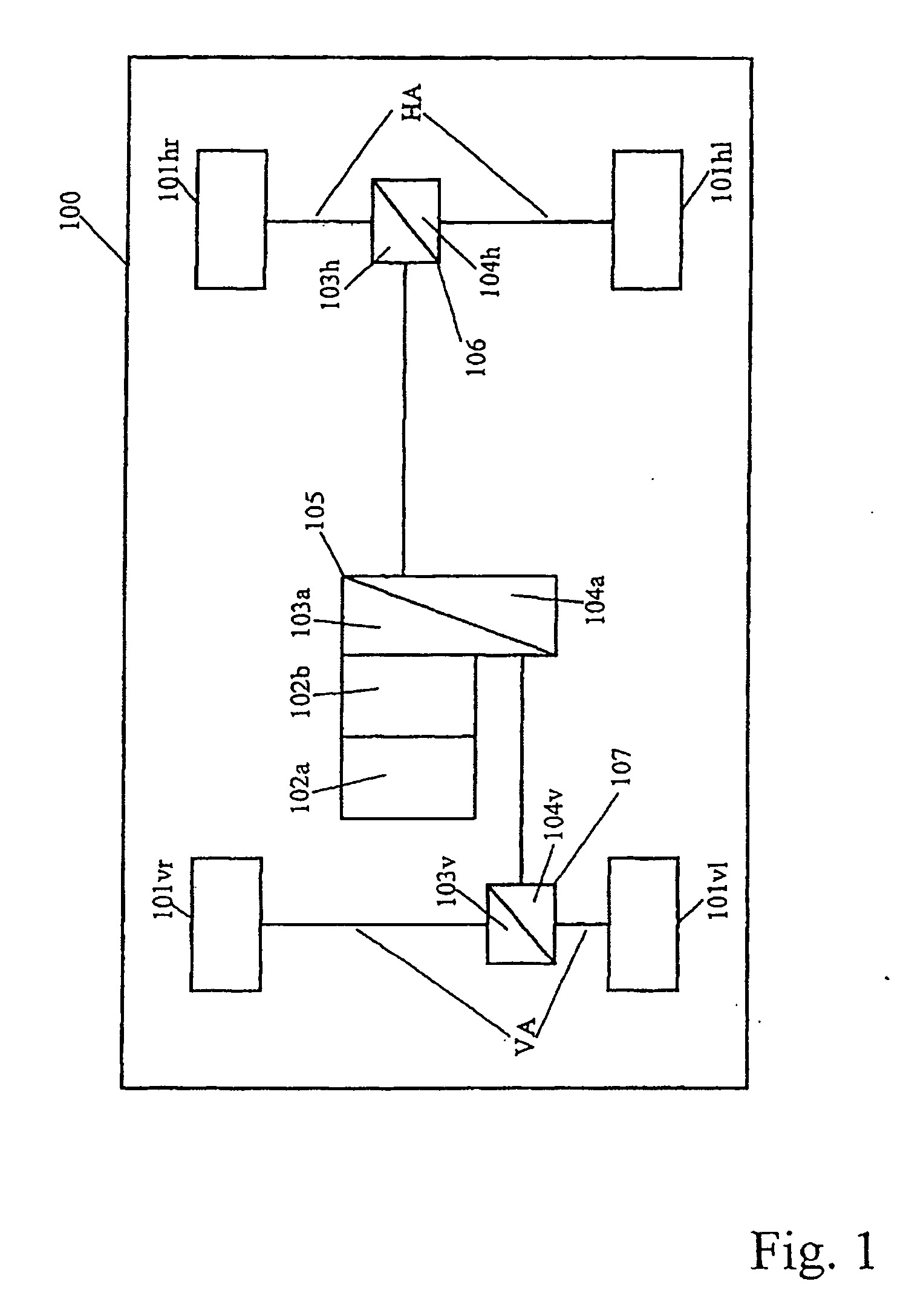
[0016] The vehicle which has a front axle and a rear axle is advantageously a vehicle with all-
wheel drive. In this vehicle, both the front axle and the rear axle are each effectively assigned a differential lock. That is to say the front axle has a differential gear mechanism with differential lock, referred to below as front axle differential gear mechanism and front axle differential lock, and the rear axle has a differential gear mechanism with differential lock, referred to below as rear differential mechanism and rear differential lock. Furthermore, in the vehicle, a further differential lock is effectively arranged between the front axle and the rear axle. In other words: the vehicle under consideration has a transfer gear, composed of a differential gear mechanism and a differential lock, for dividing the torque between the front axle and the rear axle. This differential gear mechanism and this differential lock are referred to below as longitudinal differential gear mechanism and longitudinal differential lock.
[0017] According to the invention, the operating mode of the vehicle stabilizing device is influenced as soon as the differential lock which is arranged between the front axle and the rear axle, i.e. the longitudinal differential lock, assumes an operating state other than the non-switched operating state. The influencing of the operating mode of the vehicle stabilizing device is aimed at the longitudinal differential lock for the following reason: in a vehicle with all-
wheel drive which is equipped with the abovementioned three differential locks, said locks are preselected and activated in the sequence longitudinal differential lock, then rear axle differential lock and, finally, front axle differential lock. That is to say, the longitudinal differential lock is inevitably always activated irrespective of which of the three differential locks is activated last. Consequently, for the decision as to whether or not it is necessary to influence the operating mode of the vehicle stabilizing device, it is sufficient to monitor whether the longitudinal differential lock is preselected.
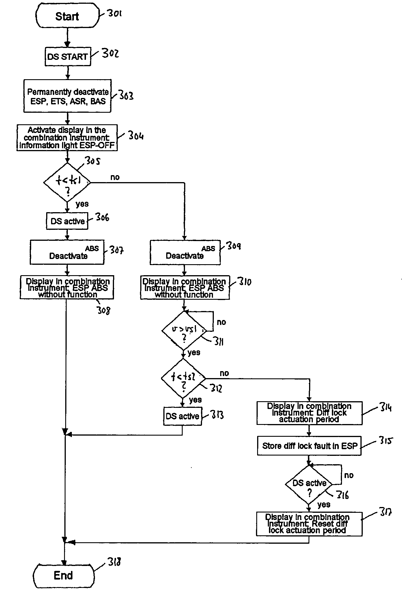
[0018] In a transition of the differential lock from the non-switched operating state into the switched operating state, the first operating state is assumed before the second operating state. Here, the switched operating state corresponds to the second operating state. In the non-switched operating state, the differential lock is not activated. In the switched operating state, the differential lock is activated. The first operating state which is specified above corresponds to a transition operating state between the non-switched operating state and the switched operating state.
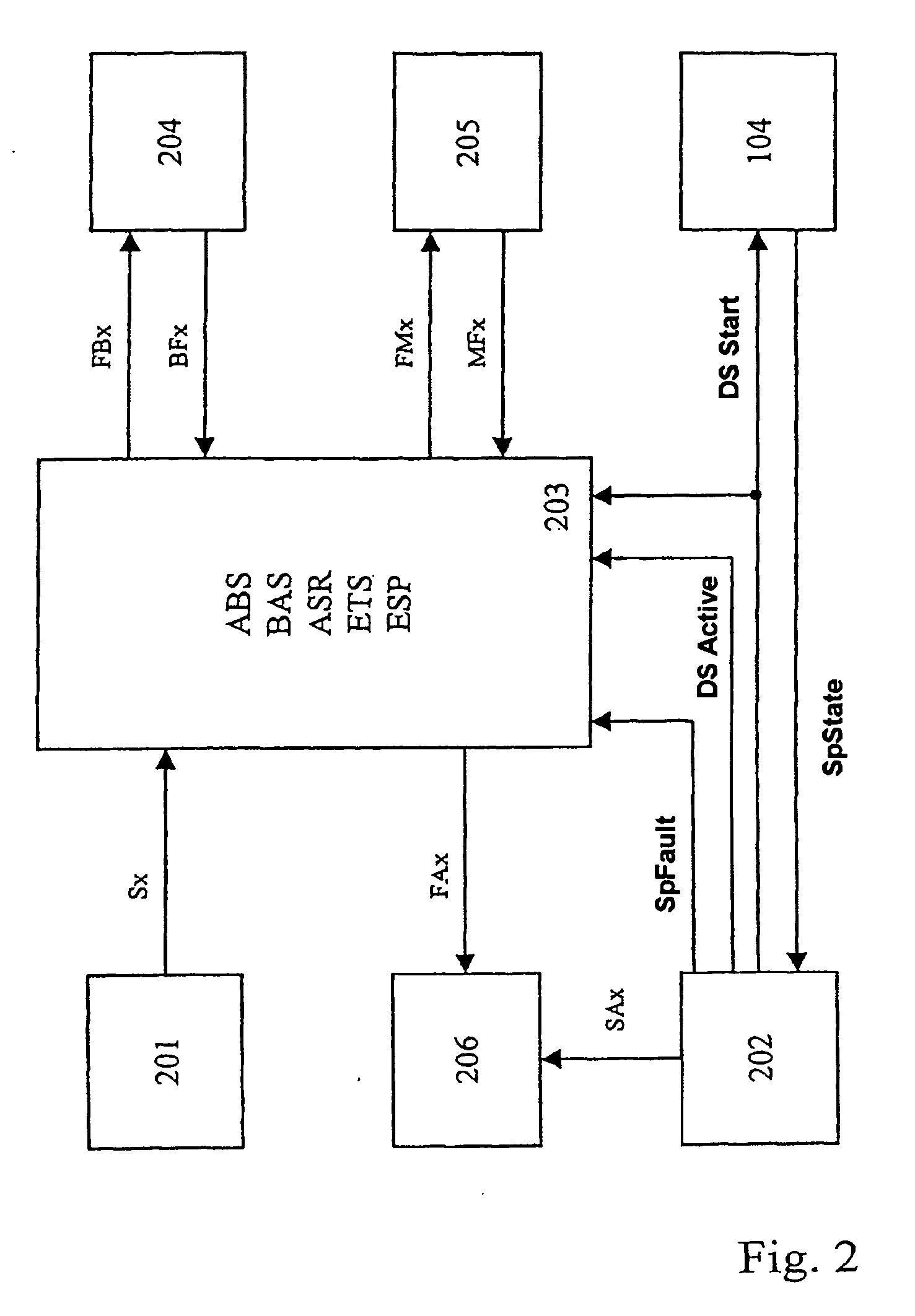
[0019] Advantageously, at least one brake slip controller (ABS) and one brake assistant (BAS) and / or one traction slip controller (ASR) and / or one electronic
traction system (ETS) and / or one vehicle movement dynamics controller (ESP) are arranged in the vehicle as vehicle stabilizing devices. In other words: the vehicle is equipped in all cases with a brake slip controller and can have any desired combination of the further vehicle stabilizing devices.

