Data replication in a storage system

Inactive Publication Date: 2005-10-13
HITACHI LTD
View PDF12 Cites 33 Cited by
  • Summary
  • Abstract
  • Description
  • Claims
  • Application Information

AI Technical Summary

Benefits of technology

[0010] According to the present invention, the above-described advantage is achieved by a storage system comprising a plurality of storage control units to which plural disk devices are connected and a data replication method thereof, wherein each of the plural storage control units includes a replication creation unit which creates replication of data of a volume in the disk devices and pair information which is information about a volume of a replication source and a volume of a replication destination; and wherein, when the replication creation unit in one of the plural storage control units is to create replication in a volume within the disk devices connected to another storage control unit, all data in the volume of the replication source is copied to the volume of the replication destination, and when the storage control unit h

Problems solved by technology

Conventionally, no technology of performing snapshot in the storage system of a cluster configuration is known.
As described above, where the storage system of the cluster configuration and the snapshot technology of the above-described prior art are combined, a storage area cannot be copied between different clusters, so that a storage area which can be used as a copy destination of a storage area and a storage area which cannot be used are formed within the storage system of one cluster configuration, causing a problem that the scalability of the storage system of the cluster configuration originally intended is impaired.
In the storage system of the cluster configuration, when it is made possible to copy a logical volume (hereinafter referred to as the volume) over clusters, namely when a copy source volume

Method used


Image

  • Data replication in a storage system
  • Data replication in a storage system
  • Data replication in a storage system

Examples


first embodiment

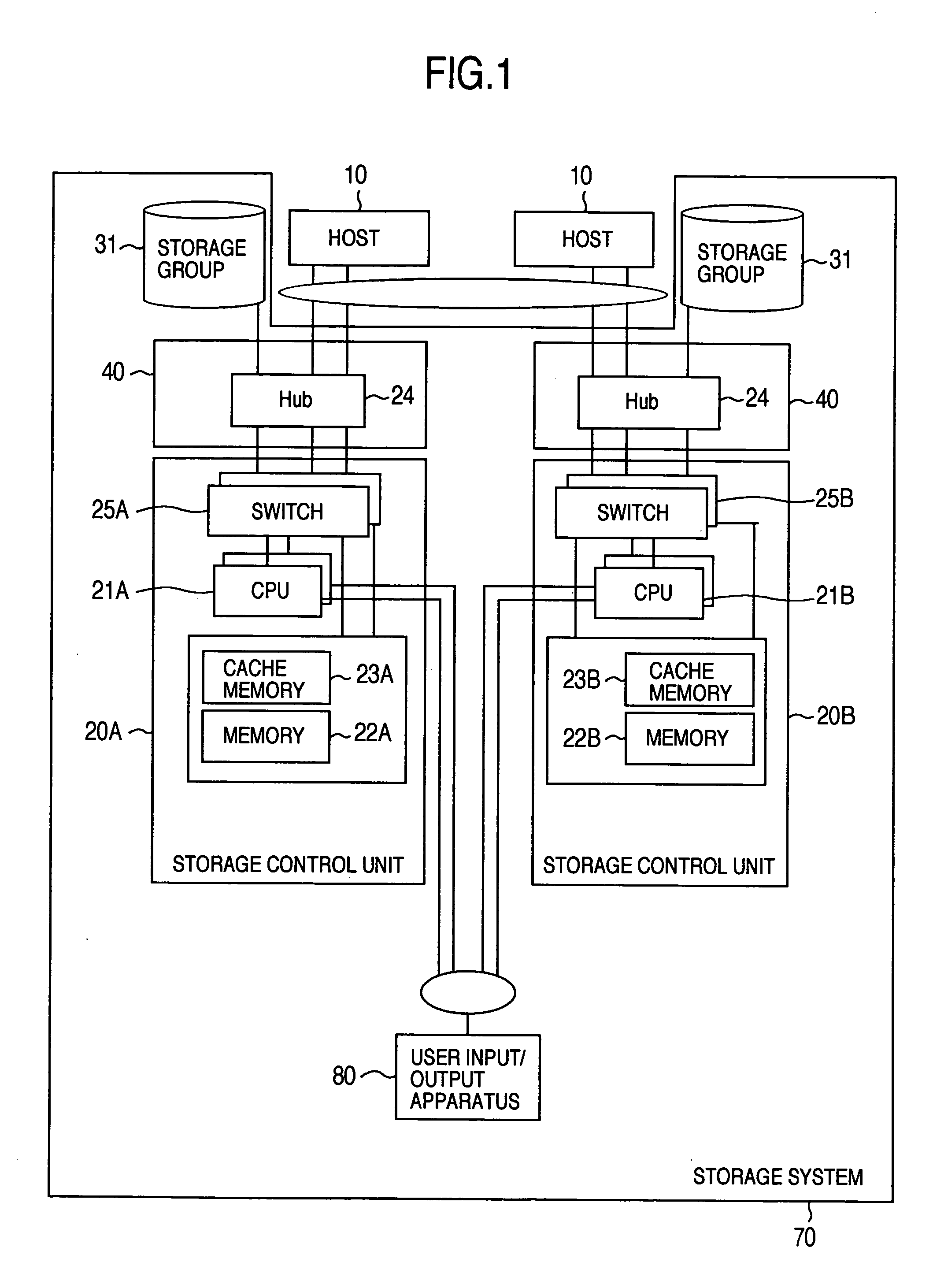
[0038]FIG. 1 is a block diagram showing a hardware configuration of a computer system including a storage system according to the present invention. In FIG. 1, numeral 10 indicates a host, numerals 20A and 20B indicate storage control units, numerals 21A and 21B indicate CPUs, numerals 22A and 22B indicate memories, numerals 23A and 23B indicate cache memories, numeral 24 indicates a hub, numerals 25A and 25B indicate switches, numeral 31 indicates a storage group, numeral 40 indicates an I / F adaptor, numeral 70 indicates a storage system, and numeral 80 indicates a user input / output apparatus.

[0039] The computer system including the storage system according to the first embodiment of the present invention is configured with the host 10 connected to the storage system 70 via the I / F adaptor 40. The storage system 70 is configured of the plural storage control units 20A, 20B, the I / F adaptor 40 connected to the individual storage control units 20A, 20B, the user input / output apparatu...

second embodiment

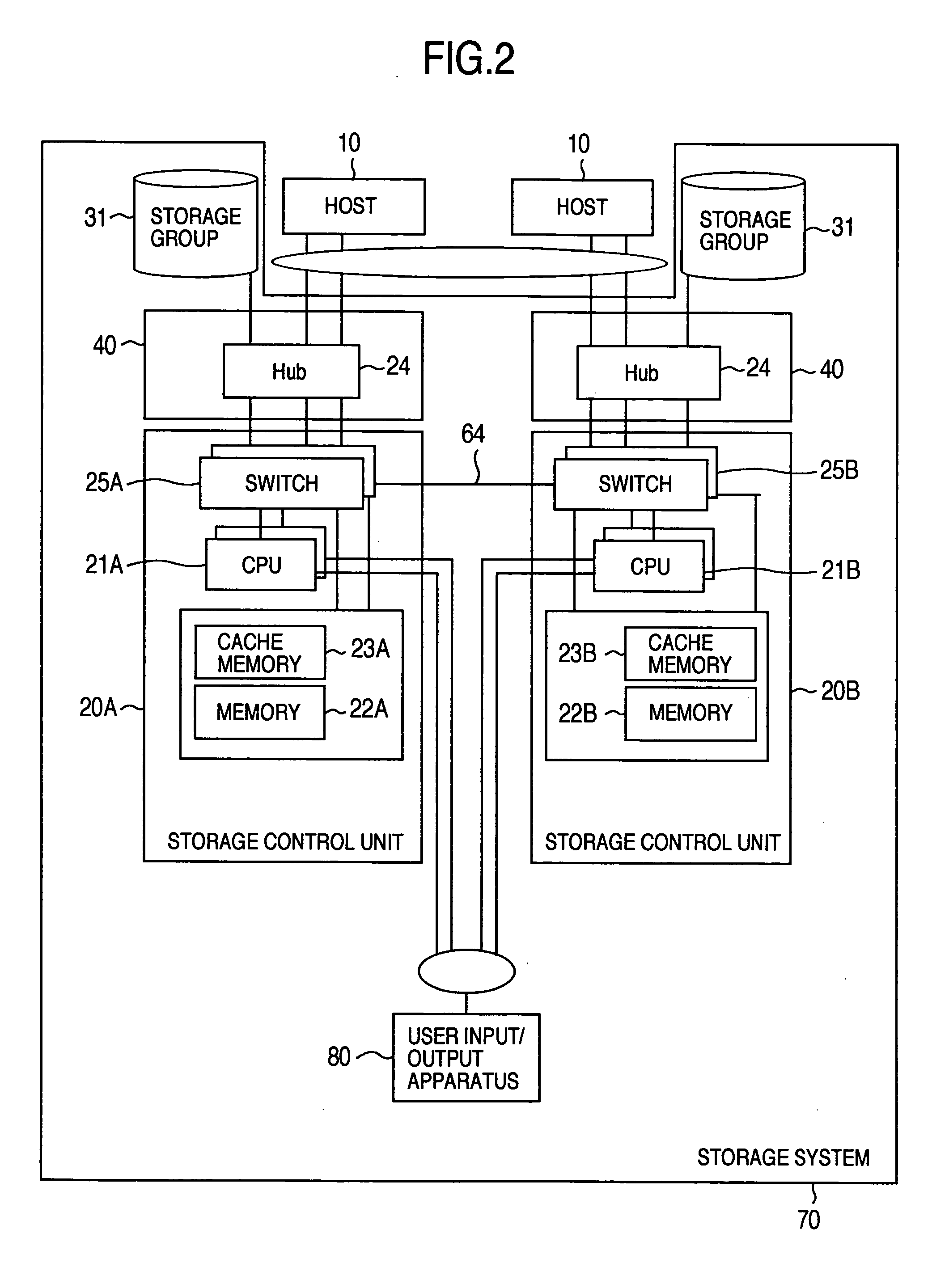
[0042]FIG. 2 is a block diagram showing a hardware configuration of a computer system including a storage system according to the present invention, and numerals in FIG. 2 are same as those in FIG. 1.

[0043] The computer system including the storage system according to the second embodiment of the present invention shown in FIG. 2 is different from the first embodiment of the present invention shown in FIG. 1 on the point that the switch 25A in the storage control unit 20A and the switch 25B in the storage control unit 20B are mutually connected, and the storage control units 20A and 20B are mutually connected. Thus, the storage control units 20A, 20B are mutually connected via the switches 25A, 25B in the second embodiment, so that the individual CPUs in the storage control units 20A, 20B can access the memory in the other storage control unit.

[0044] For example, the CPU 21A of the storage control unit 20A can access the memory 21B in the storage control unit 20B via the switch 25....

third embodiment

[0045]FIG. 3 is a block diagram showing a structure of the storage system according to the present invention. In FIG. 3, numeral 25 indicates a device interface, numeral 32 indicates a storage group, numeral 50 indicates a processor, numerals 60 to 63 indicate networks, numeral 510 indicates a configuration information table, and other numerals are same as those in FIG. 1.

[0046] The computer system including the storage system according to the third embodiment of the present invention shown in FIG. 3 is configured with a first storage system 70A connected to the host 10 via the network 60 and the first storage system 70A and a second storage system 70B connected via the network 61. A user input / output apparatus 80 can be connected to each part in the first storage system 70A via the management networks 62, 63. The first and second storage systems 70A, 70B are configured in the same way, but only the first storage system 70A is shown its inside structure in FIG. 3, and the inside str...


PUM


Abstract

For a storage system having plural control units to which plural disk devices are connected, in the method for creating replication in a volume of the disk devices connected to different control units, when receiving update I/O of a replication source during an initial copy for replication, the reflection of update to the replication destination is performed on an extension of the same I/O. When a pair is divided after the completion of copying, the update position is retained on the differential bitmap disposed in the individual control units, and the differential bitmap is merged to one of the control units at a time of resynchronization to perform copy processing.

Description

[0001] The present application claims priority from Japanese application JP 2004-115693 filed on Apr. 9, 2004, the content of which is hereby incorporated by reference into this application. BACKGROUND OF THE INVENTION [0002] The present invention relates to a storage system and a data replication method, and more particularly to a storage system comprising plural storage control units to which plural disk devices are connected, and a data replication method for creation of replication. [0003] Recently, demands for the reduction of time necessary for processing to create replication (hereinafter referred to as the backup) of data stored in a storage device of a storage system possessed by corporations in another storage device are increasing. Such demands are backed by the reduction of time allocated to the backup processing because an amount of information possessed by the corporations is increasing and the time for backup is increasing while business hours of corporations are exte...

Claims


Application Information

Patent Timeline
IPC IPC(8): G06F11/14G06F3/06G06F12/00G06F12/16
CPCG06F11/2082G06F11/2069
Inventor SATOYAMA, AIMORISHITA, NOBORUYAMAMOTO, YASUTOMO
Owner HITACHI LTD
Why Eureka
Try Eureka