Combination knife

a technology of combination knife and combination blade, which is applied in the direction of metal working apparatus, etc., can solve the problems of difficult stomach opening and more complicated operation

Inactive Publication Date: 2005-10-20
EKA KNIVAR
View PDF13 Cites 26 Cited by
  • Summary
  • Abstract
  • Description
  • Claims
  • Application Information

AI Technical Summary

Benefits of technology

[0009] The combination knife includes stop means for preventing further rotation of the common blade member relative to the knife handle, after the blade member has been rotated in a direction in which one of the two cutting sections has been brought to a position for use. The cutting edge of the conventional, knife-acting cutting section and the cutting edge of the stomach-opening cutting section are each located along one and the same edge of the common blade member.

Problems solved by technology

It is, of course, possible to use a knife instead of a stomach opener, but this is a more complicated operation.
This makes opening of the stomach difficult to achieve.

Method used


Image

  • Combination knife
  • Combination knife
  • Combination knife

Examples


first embodiment

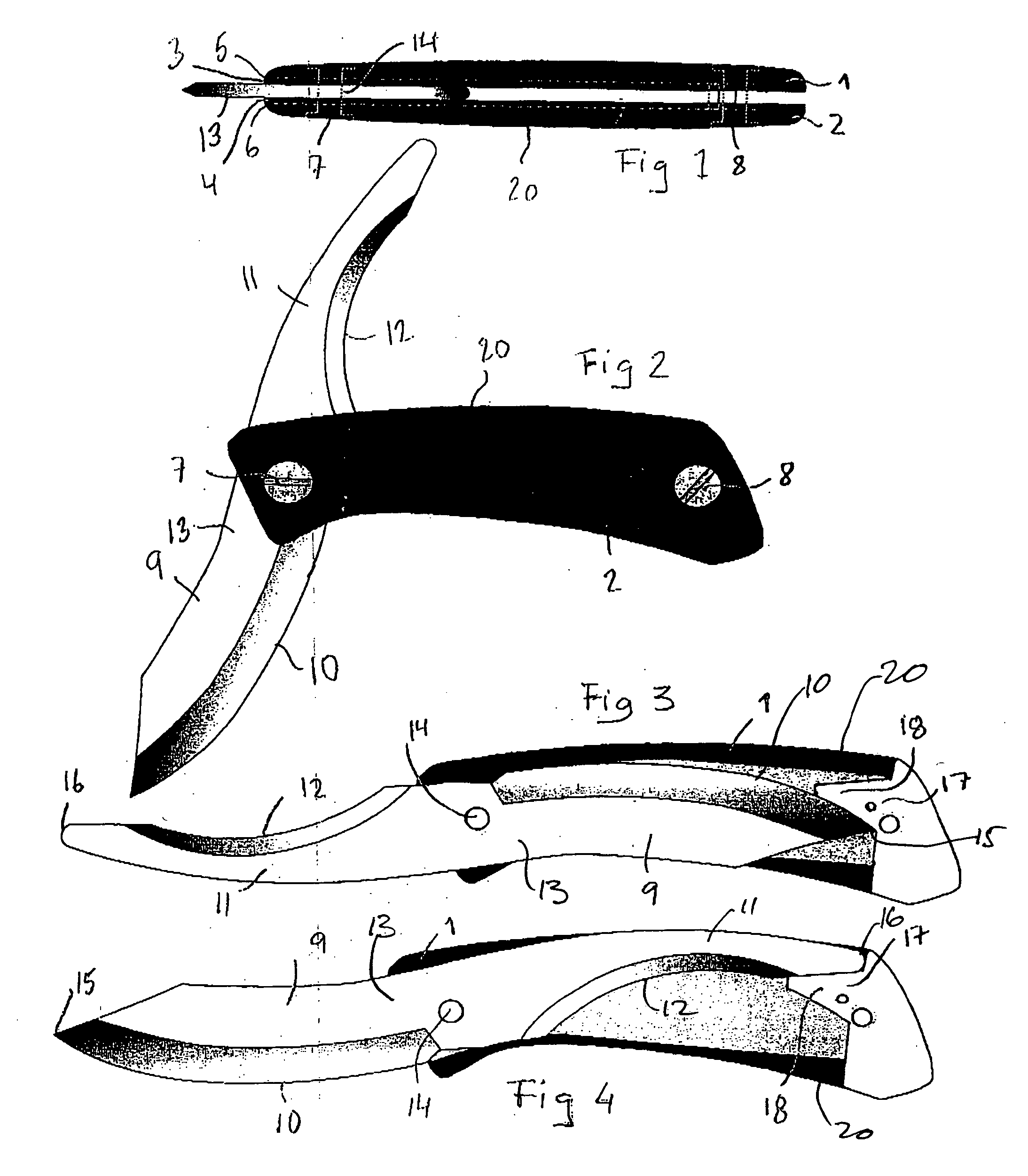
[0022] According to the invention, as shown in FIGS. 2 through 4, the combined knife includes a stop means 17 for limiting movement of the common blade member 13 in relation to the knife handle 20 when one of the two above-mentioned blade elements has been turned to a use position.

[0023] According to one preferred embodiment of the invention, the stop means 17 includes a shoulder 18 that projects inwardly between the handle side members 1, 2 and is fixed relative to the handle 20. The shoulder 18 is located at that end of the knife handle 20 that is opposite to the end at which the pivot joint 14 is located. The shoulder 18 projects inwardly sufficiently far between the handle side members 1, 2 to prevent the common blade member 13 from being rotated beyond the shoulder 18.

[0024]FIG. 3 shows the use position of the stomach-opening blade 11, in which the outer end 15 of cutting edge 10 of the blade element 9 lies in abutment with the shoulder 18. When using the stomach-opening blade...

second embodiment

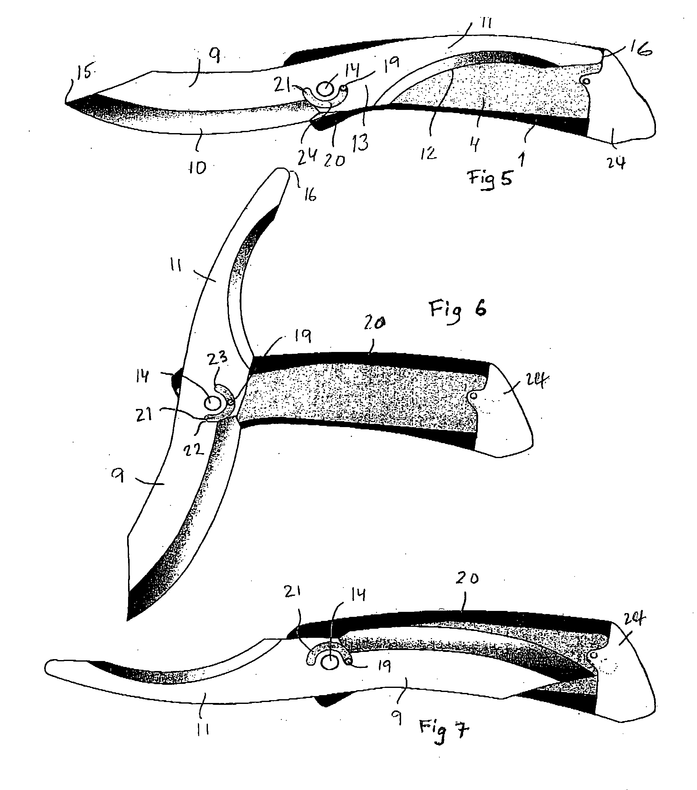
[0027] According to the invention, shown in FIGS. 5 through 7, the combination knife includes a different form of stop means for preventing rotation of the common blade member 13 relative to the knife handle 20 when one of the two cutting edges has been brought to a use position. The stop means 24 includes a through-penetrating channel 21 formed in the common blade member 13, the channel extending in an arcuate path with the center of the arc coinciding with the center of the pivot joint 14. A pin 19 extends between the handle side members 1, 2 and through the channel 21, wherein the channel 21 is configured such that when the common blade member 13 is rotated so that the pin 19 abuts one end 22 (see FIG. 6) of the channel 21 or the other end 23 of said channel, the stomach-opening blade element 11 or the knife acting blade 9, respectively, will be in its use position. The pin 19 can extend through the handle side members or only through the sheet metal elements 3, 4.

[0028] A should...


PUM


Abstract

A combination knife including a common blade member that carries two different blade elements having cutting edges, each blade element located on a respective side of a pivot joint carried in a knife handle and around which the common blade member can be rotated. One blade element includes a conventional knife-acting cutting edge, while the other blade element includes a stomach-opening cutting edge situated on the upper edge of the blade element when in its use position. A stop is provided for preventing rotation of the common blade member relative to the handle after rotation of the common blade member in a direction such that one of the two cutting edges has been brought to its use position. The cutting edge of the knife-acting blade element and that of the stomach-opening blade element are situated along the same edge of the common blade member.

Description

BACKGROUND OF THE INVENTION [0001] 1. Field of the Invention [0002] The present invention relates to a combination knife, and more particularly to a hunting knife. [0003] 2. Description of the Related Art [0004] An animal killed on a hunting expedition is conveniently positioned so that desired parts of the animal, or quarry, can be removed on site. In this regard, the abdominal cavity of the animal is normally cut open and the animal's intestines then removed. There is typically used for this purpose a so-called stomach-opening device, which is a knife-like tool that includes a cutting edge on the upper side of the knife-acting blade. A stomach opener is used, because it is desired to avoid damaging the intestines. It is, of course, possible to use a knife instead of a stomach opener, but this is a more complicated operation. [0005] However, when opening the stomach or abdominal cavity of an animal, a conventional knife is also used in the majority of cases to cut away the animal's...

Claims


Application Information

Patent Timeline
Patent Type & Authority Applications(United States)
IPC IPC(8): B26B1/04B26B21/02
CPCB26B1/02
Inventor NORDQVIST, STIGKARLSSON, ARNE
Owner EKA KNIVAR
Why Eureka
Try Eureka