Impeller for data acquisition in a flow

a technology of data acquisition and impeller, which is applied in the direction of instruments, instruments, and borehole/well accessories, etc., can solve the problems of high cost, complex and expensive assembly of impeller and magnet, and high cost of structur

Inactive Publication Date: 2005-10-20
SCHLUMBERGER TECH CORP
View PDF5 Cites 14 Cited by
  • Summary
  • Abstract
  • Description
  • Claims
  • Application Information

AI Technical Summary

Benefits of technology

[0011] The purpose of this invention is to propose an impeller for data acquisition in a flow that does not have the disadvantages mentioned above.
[0012] One purpose of the invention is to propose an impeller that is particularly easy to make and is inexpensive while being very high performance.
[0013] Another purpose of the invention is to propose an impeller that is light weight, that has a low inertia force to start rotation even with very flow fluid velocities.
[0014] Another purpose of the invention is to propose an impeller that resists the corrosive fluid in which it is immersed, even if it contains sand or debris.

Problems solved by technology

At the moment, impellers are made of metal or a plastic material by machining and the cost is relatively high.
The assembly consisting of the impeller and the magnet then become complicated and expensive because a protective chamber has to be provided for the magnet.
This structure also has a high cost.

Method used


Image

  • Impeller for data acquisition in a flow
  • Impeller for data acquisition in a flow
  • Impeller for data acquisition in a flow

Examples


Embodiment Construction

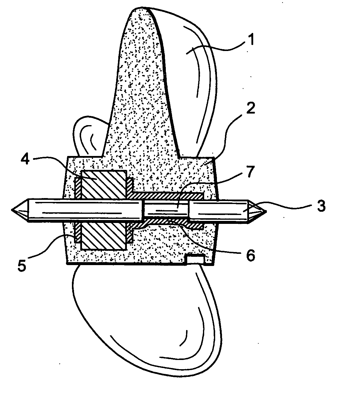
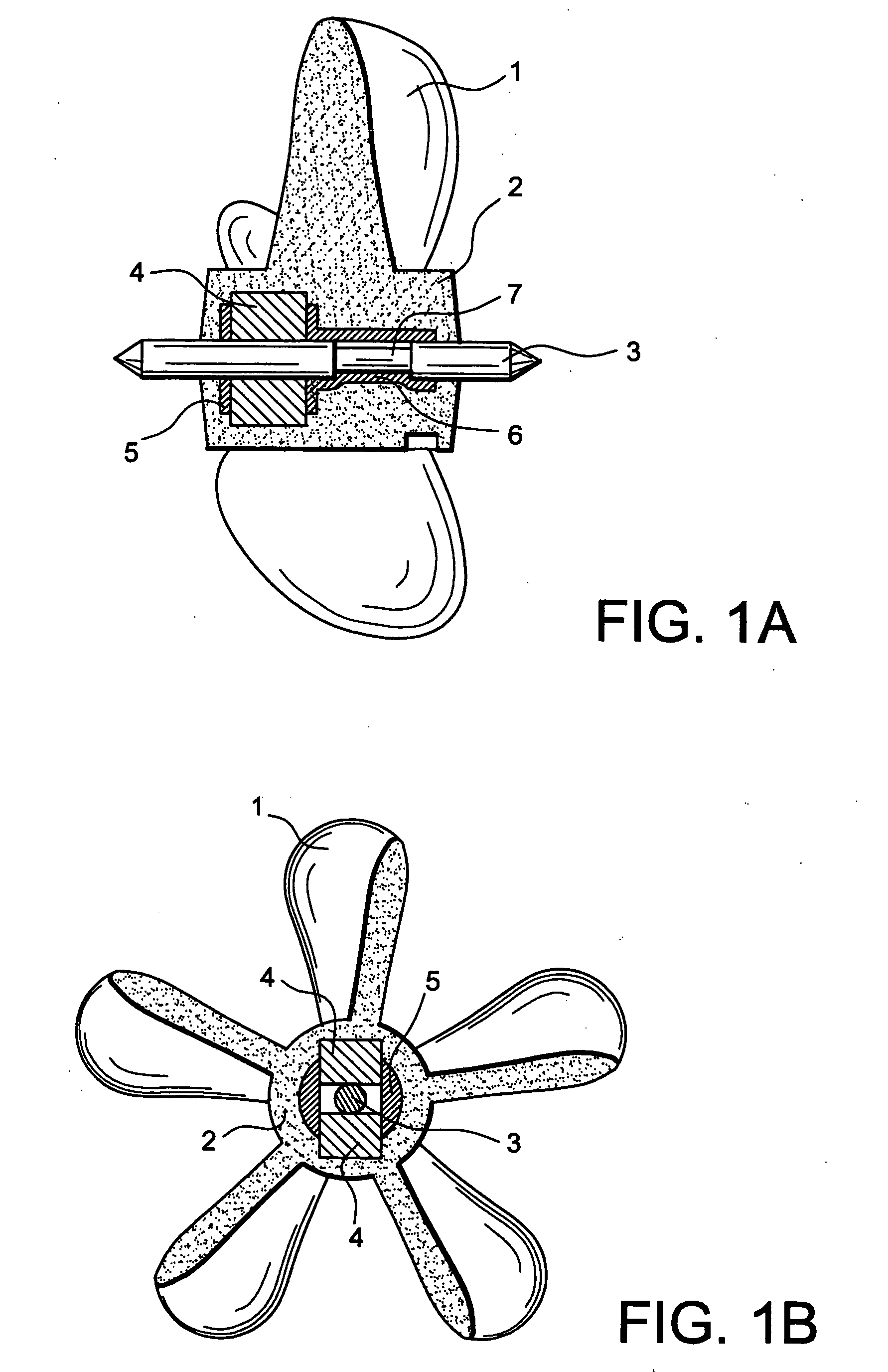
[0029] The impeller shown in FIGS. 1A, 1B have blades 1, for example five blades, and a hub 2. This number of five blades is not limitative, it would be possible for the impeller to have more blades 1 or less blades 1. However, an odd number is preferable to give a more uniform rotation, with the impeller support never concealing more than one blade at a time.

[0030] According to one characteristic of the invention, the impeller made of a plastic material is insert moulded, trapping a spindle 3 and at least one magnet 4 in its hub 2. The magnet 4 is housed in an insert 5 that is also trapped in the hub 2 of the impeller.

[0031] In this context, the term insert moulding means that the moulded material contains at least one “trapped body” inside it.

[0032] By insert moulding the impeller around the spindle 3, at least one magnet 4 and the insert 5, a particularly compact assembly is obtained that is both inexpensive and has a high performance. The manufacturing cost can be reduced by ...


PUM


Abstract

This invention relates to an impeller for data acquisition in a flow. It comprises blades (1) and a hub (2). It is made of a plastic material and it is insert moulded by trapping a spindle (3) and at least one magnet (4) in its hub (2). Application particularly for data acquisition in hydrocarbon wells.

Description

TECHNICAL DOMAIN [0001] This invention relates to an impeller for use on a data acquisition instrument in a flow and an instrument for data acquisition equipped with such an impeller. STATE OF PRIOR ART [0002] It is required to acquire a number of data about the multiphase fluid that flows in a well as precisely as possible, in order to perform maintenance functions, particularly in hydrocarbon production wells. For example, these data may include the nature, the flow and the proportion of the different phases in the fluid. In a hydrocarbon production well, there is usually a three-phase fluid formed of oil, gas and water. These fluid phases do not have the same density, they do not move at the same velocity, they are not present in the same proportions and they do not enter the well at the same location. The distribution of the different fluid phases in the flow is different depending on whether the well is vertical, inclined or horizontal. Due to the difference in density in the d...

Claims


Application Information

Patent Timeline
Patent Type & Authority Applications(United States)
IPC IPC(8): E21B47/10G01F1/115
CPCG01F1/115
Inventor CENS, FABIENGALLAND, GILBERTCHYZAK, JEAN-PIERRE
Owner SCHLUMBERGER TECH CORP
Why Eureka
Try Eureka