Cnc slitter machine
a slitter machine and slitting technology, applied in the field of slitter machines, can solve the problems of requiring a high degree of skill, affecting the operation of the slitter machine, and requiring a large degree of skill, so as to achieve convenient and efficient reconfiguration, avoid significant machine downtime and labor-intensive procedures, and facilitate the effect of slitting
- Summary
- Abstract
- Description
- Claims
- Application Information
AI Technical Summary
Benefits of technology
Problems solved by technology
Method used
Image

Examples
first embodiment
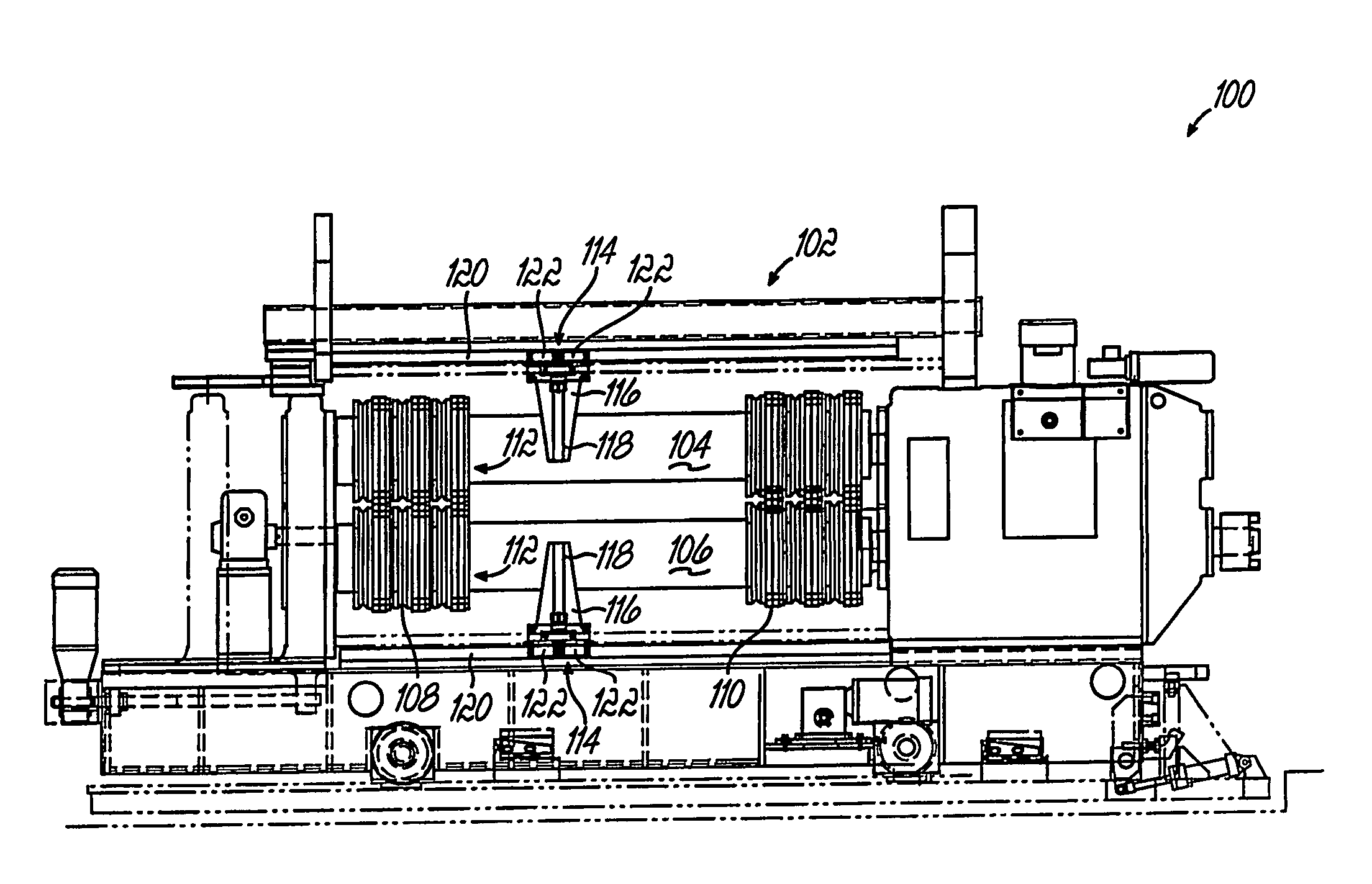
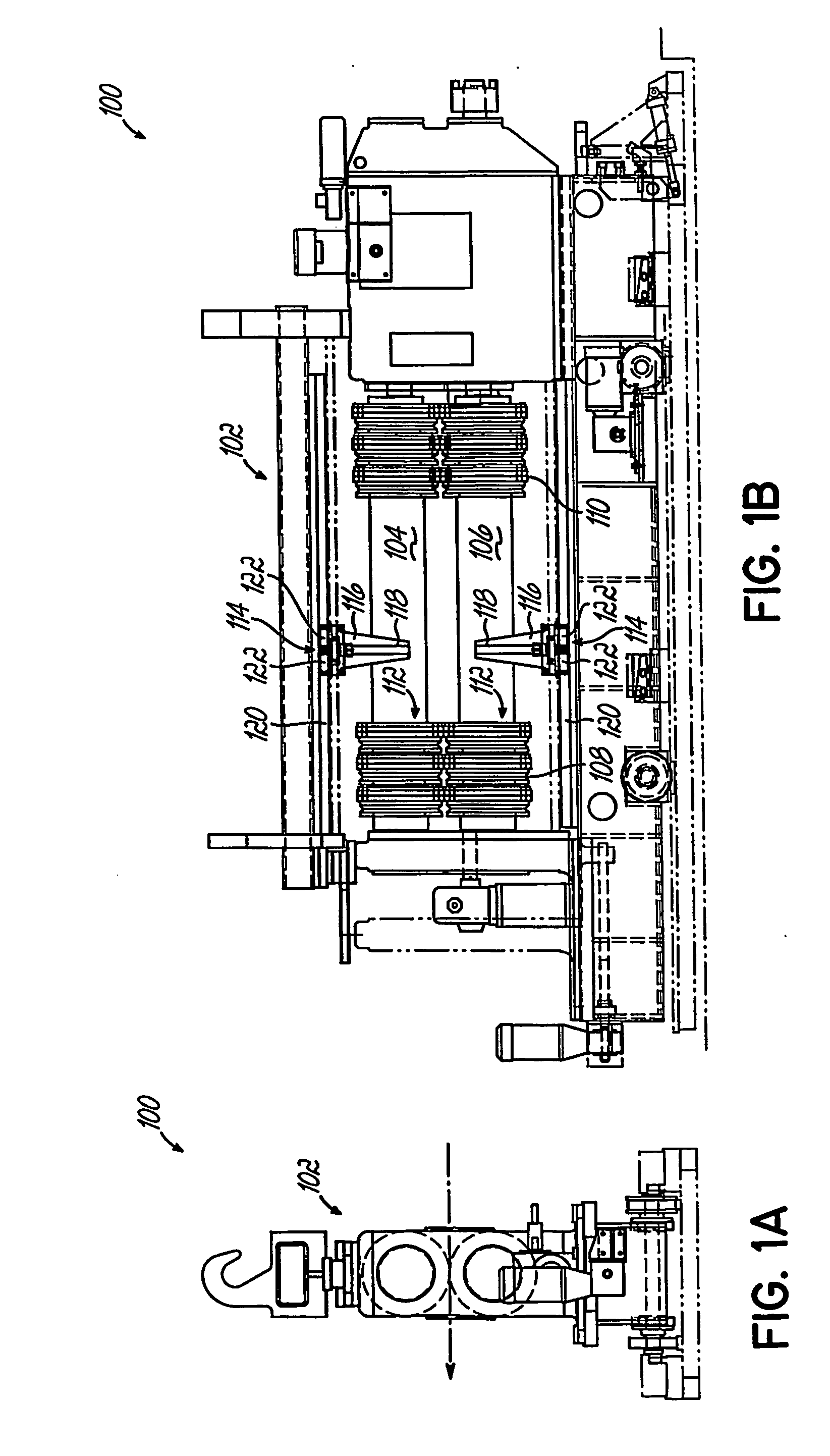
[0048] Referring to FIGS. 1A and 1B, a CNC slitting machine 100 according to the present invention is used for shearing metal sheet, such as sheet steel, into multiple segments or mults of a desired width along slits. The metal sheet is normally provided from a mill or other supplier of mill products In a coil. The coil is supported on a spool. The metal sheet is withdrawn from the coil and fed into the machine 100. Typically, the metal sheet passes through a straightening machine to remove the coil set. The sheet alternatively may be fed into the machine 100 in individual sections, preferably with the assistance of a skewed roller table (not shown) or the like.
[0049] In accordance with one embodiment of the present invention, as shown in FIGS. 1A and 1B, slitting machine 100 includes a frame 102 and upper and lower arbors 104, 106, respectively, mounted therein for rotation. The arbors 104, 106 are supported in the frame 102 by conventional bearings and are coupled In a conventiona...
second embodiment
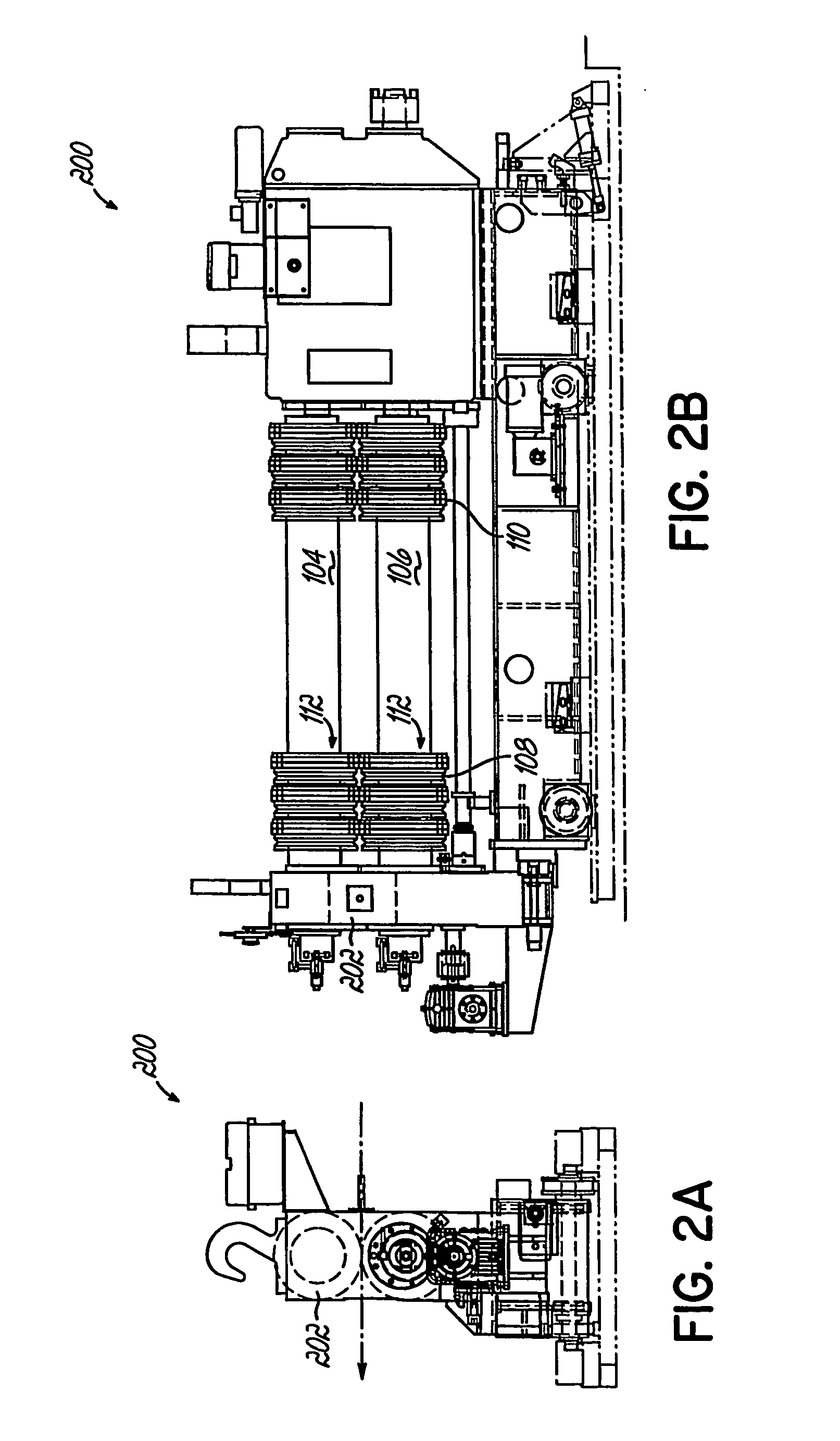
[0060] Referring now to FIGS. 2A and 2B, a CNC slitting machine 200 in accordance with the present invention is shown, where like numerals represent like parts to the CNC slitting machine 100 of FIG. 1. In this embodiment, a portion of the frame, i.e., the left side of the frame 202 as shown in FIG. 2B, pivots or swings out to permit knife assemblies 112 to be added or removed from the upper and lower arbors 104, 106 In similar fashion to FIG. 1. The positioning of knife assemblies 112 Is the same as found in CNC slitting machine 100.
third embodiment
[0061] Referring now to FIGS. 3A and 3B, a CNC slitting machine 300 in accordance with the present invention is shown, where like numerals represent like parts to the CNC slitting machine 100 of FIG. 1. In this embodiment, the frame 302 comprises an upper frame 302a movably coupled at spaced ends thereof to a lower frame 302b. The upper and lower frames 302a, 302b of the machine 300 include the upper and lower arbors 104,106, respectively, mounted therein for rotation. A pair of jack screws 304 are positioned between spaced opposite ends of the upper and lower frames 302a, 302b of the slitting machine 300. The Jack screws 304 are positioned between the upper and lower frames 302a, 302b proximate a front of the machine 300. The upper and lower frames 302a, 302b are pivotally coupled together around a pivot shaft 306 proximate the back of the machine 300. The lower frame 302b Is stationary while the upper frame 302a is capable of pivotal movement relative to the lower frame 302b about...
PUM
| Property | Measurement | Unit |
|---|---|---|
| Circumference | aaaaa | aaaaa |
Abstract
Description
Claims
Application Information
 - Generate Ideas
- Intellectual Property
- Life Sciences
- Materials
- Tech Scout
- Unparalleled Data Quality
- Higher Quality Content
- 60% Fewer Hallucinations
Browse by: Latest US Patents, China's latest patents, Technical Efficacy Thesaurus, Application Domain, Technology Topic, Popular Technical Reports.
© 2025 PatSnap. All rights reserved.Legal|Privacy policy|Modern Slavery Act Transparency Statement|Sitemap|About US| Contact US: help@patsnap.com