Fluid controller

a technology of flue control and controller, which is applied in the direction of lighting and heating apparatus, valve housing, pipe heating/cooling, etc., can solve the problems of increasing the number of construction steps in situ, taking a long time to assemble the components including the heating device, and prolonging the shutdown period, so as to achieve the effect of greater ease of adding or modifying lines

Inactive Publication Date: 2005-10-20
CKD +1
View PDF19 Cites 402 Cited by
  • Summary
  • Abstract
  • Description
  • Claims
  • Application Information

AI Technical Summary

Benefits of technology

[0007] In assembling the fluid control apparatus according to the first aspect of the invention in its entirety, lines are built by mounting coupling members and fluid control devices on line support members, arranging tape heaters on opposite sides of one or some of these lines which need to be heated and causing clips to hold the heaters to each line from opposite sides. The lines are then installed on a base member. Thus, the apparatus is easy to assemble. The line equipped with no heating device can be modified into a line having tape heaters merely by upwardly removing channel connecting means as required, removing the old line to be modified as mounted on the line support member, attaching the line support member of a heater-equipped line to the base member, and providing channel connecting means necessary for the modification. Thus, the line having heating device is available easily. Lines having the tape heaters can be added similarly with ease.
[0009] When the fluid control apparatus embodying the second aspect of the invention is to be assembled in its entirety, the apparatus can be assembled easily by inserting sheath heaters into the heater bores of each of line support members, mounting coupling members and fluid control devices on these line support members to build lines, and installing the lines on a base member. Further a line equipped with no heating device can be modified into a line having sheath heaters merely by upwardly removing channel connecting means as required, removing the old line to be modified as mounted on the line support member, replacing the line support member by a line support member having sheath heaters, attaching the new support member to the base member, and providing channel connecting means necessary for the modification. Thus, the line having the heating device is available easily. Lines having sheath heaters can be added similarly with ease.
[0011] According to the first and second aspects of the invention, rails of various shapes, for example, are usable as line support members. In such a case, the line support member is a rail removably attached to the base member, and each of the coupling members is slidably mounted on the line support member. Preferably, each of the fluid control devices is mounted on at least two adjacent coupling members. Coupling members, fluid control devices and tape heaters can then be provided on the line support member by slidingly moving the coupling members along the path of the line support member to a required position, thereafter mounting the fluid control devices each on at least two adjacent coupling members and causing clips to hold the tape heaters. Thus, the line equipped with tape heaters can be assembled easily.
[0012] The base member may be in the form of a frame using rails (of nonmetallic material) for making line support members and using inlet-side rails, outlet-side rails and connectors interconnecting these rails. Lines can then be modified by upwardly removing channel connecting means as required, removing the oil line to be modified as mounted on the line support member, slidingly moving as required the support member for the line not to be modified, installing the line support member of the line to be substituted on the base member, further slidingly returning to a proper position the line support member for the line not to be modified, and finally installing channel connecting means required for the modification. Lines can be additionally provided similarly. Consequently, lines can be added or modified with greater ease. The nonmetallic material used for the rails of the base member permits the base member to produce a heat insulating effect, eliminating the need to provide an additional heat insulating layer.

Problems solved by technology

The conventional fluid control apparatus of the type described has the problem that it takes much time to assemble the components including the heating device.
Another problem encountered is that since full consideration is not given to the additional provision of lines or modification of lines, there arises a need to remove all members as mounted on the base plate for replacement by a base plate having required members mounted thereon when the system is to be rebuilt, consequently entailing a prolonged period of shutdown and an increased number of construction steps in situ.

Method used


Image

  • Fluid controller
  • Fluid controller
  • Fluid controller

Examples


Embodiment Construction

[0020] Embodiments of the invention will be described below with reference to the drawings.

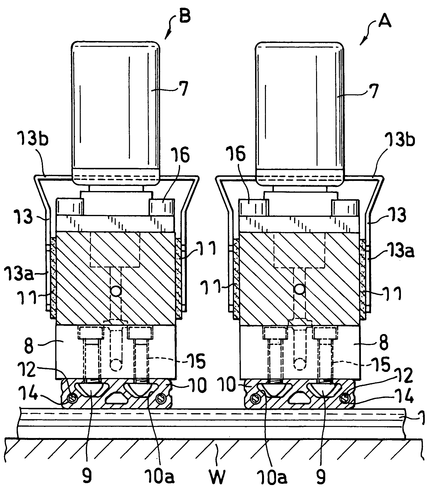
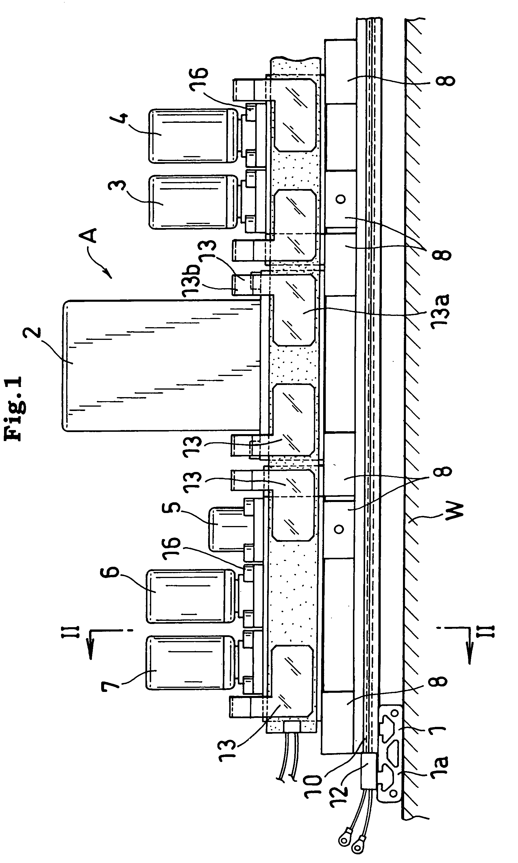
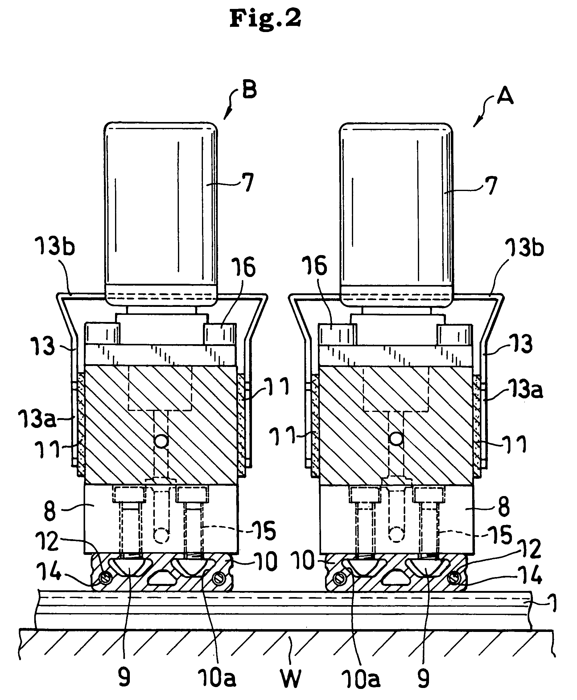
[0021] FIGS. 1 to 4 show a first embodiments of the invention, i.e., a fluid control apparatus, comprising a plurality of lines A, B arranged in parallel on a base member 1, with their inlets, as well as their outlets, facing toward the same direction. (Two line A, B are shown in FIG. 2.) Each of these lines A, B (line A only shown in FIG. 1) comprises a plurality of fluid control devices 2, 3, 4, 5, 6, 7 arranged in an upper stage and a plurality of block coupling members 8 arranged in a lower stage. Each line A or B is mounted on a line support member 10. Each line A or B can be heated by a first heating device comprising tape heaters 11 shown in FIG. 3 and a second heating device comprising sheath heaters 12 shown in FIG. 4.

[0022] The fluid control devices of the line A shown in FIG. 1 are a mass flow controller 2; inlet-side first shut-off valve 3 and inlet-side second shut-off valve 4 w...


PUM


Abstract

Each of lines A, B is provided on each of opposite sides thereof with a tape heater 11, and a space for positioning a tape heater holding clip 13 therein is provided in each of locations between adjacent fluid control devices. The tape heaters 11 are held from opposite sides thereof to the line by the clip 13. The lines A, B provided with the heaters are each mounted on a line support member 10 removably attached to a base member 1. The line support member 10 has a heater insertion bore 14 formed therein and extending longitudinally thereof. A sheath heater 12 is inserted into the bore 14.

Description

TECHNICAL FIELD [0001] The present invention relates to fluid control apparatus for use in semiconductor fabrication equipment, and more particularly to fluid control apparatus which require heating of a fluid. [0002] As to the terms “front,”“rear,”“upper” and “lower” as used herein, the right-hand side of FIG. 1 will be referred to as “front,” the left-hand side thereof as “rear,” and the upper and lower sides of the same drawing as “upper” and “lower,” respectively. The terms “left” and “right” are used for the apparatus as it is seen from the front rearward. However, the terms “front,”“rear,”“upper” and “lower” are used for the sake of convenience; the apparatus may be used with their front and rear sides reversed in position or with their upper and lower sides positioned as the left and right sides. BACKGROUND ART [0003] Fluid control apparatus for use in semiconductor fabrication equipment are made integrated by connecting a mass flow controller and shut-off valves without usin...

Claims


Application Information

Patent Timeline
Patent Type & Authority Applications(United States)
IPC IPC(8): F16K27/00F17D3/01F16K49/00F24H1/10F24H1/12F24H9/18
CPCF16K27/003F24H9/1863F24H1/121F16K49/002Y10T137/6606Y10T137/87885F24H2250/02
Inventor HOSHI, GEORGEOKABE, TSUNEYUKIGOSHIMA, KENICHIKOBAYASHI, HIDEONAGAYA, AKINORIYAMAJI, MICHIOYOSHIKAWA, KAZUHIROKAWANO, YUJI
Owner CKD
Why Eureka
Try Eureka