
Wave energy converter (WEC) with magnetic braking

Inactive Publication Date: 2005-10-20
OCEAN POWER TECHNOLOGIES
View PDF7 Cites 23 Cited by
  • Summary
  • Abstract
  • Description
  • Claims
  • Application Information

AI Technical Summary

Benefits of technology

[0005] In accordance with the invention, the problem of excessive motion may be eased by using electromagnetic means to brake and / or dampen motion between the shell and the column when they move beyond certain points relative to each other.

Problems solved by technology

For example, the forces of the waves may be of such a magnitude (e.g., during a storm) that the travel of the float relative to the column may exceed a desired “operating range” and may, if not blocked, cause separation of the float from the column.
That is, the float may become detached, or torn, from the column.
Reliance on mechanical stops and / or dampers is generally not satisfactory because of the cost and because they are subject to wear and breakdowns due to the forces applied to them.
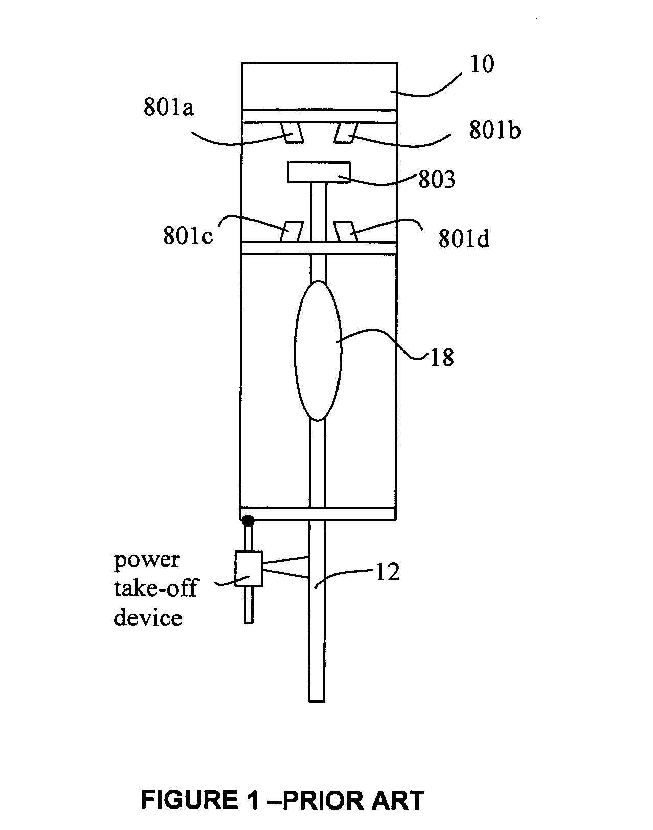
Stops and / or dampers are shown in FIG. 1, but a similar problem exists with hydraulic and / or other mechanical systems.

Method used


Image

  • Wave energy converter (WEC) with magnetic braking
  • Wave energy converter (WEC) with magnetic braking
  • Wave energy converter (WEC) with magnetic braking

Examples


Embodiment Construction

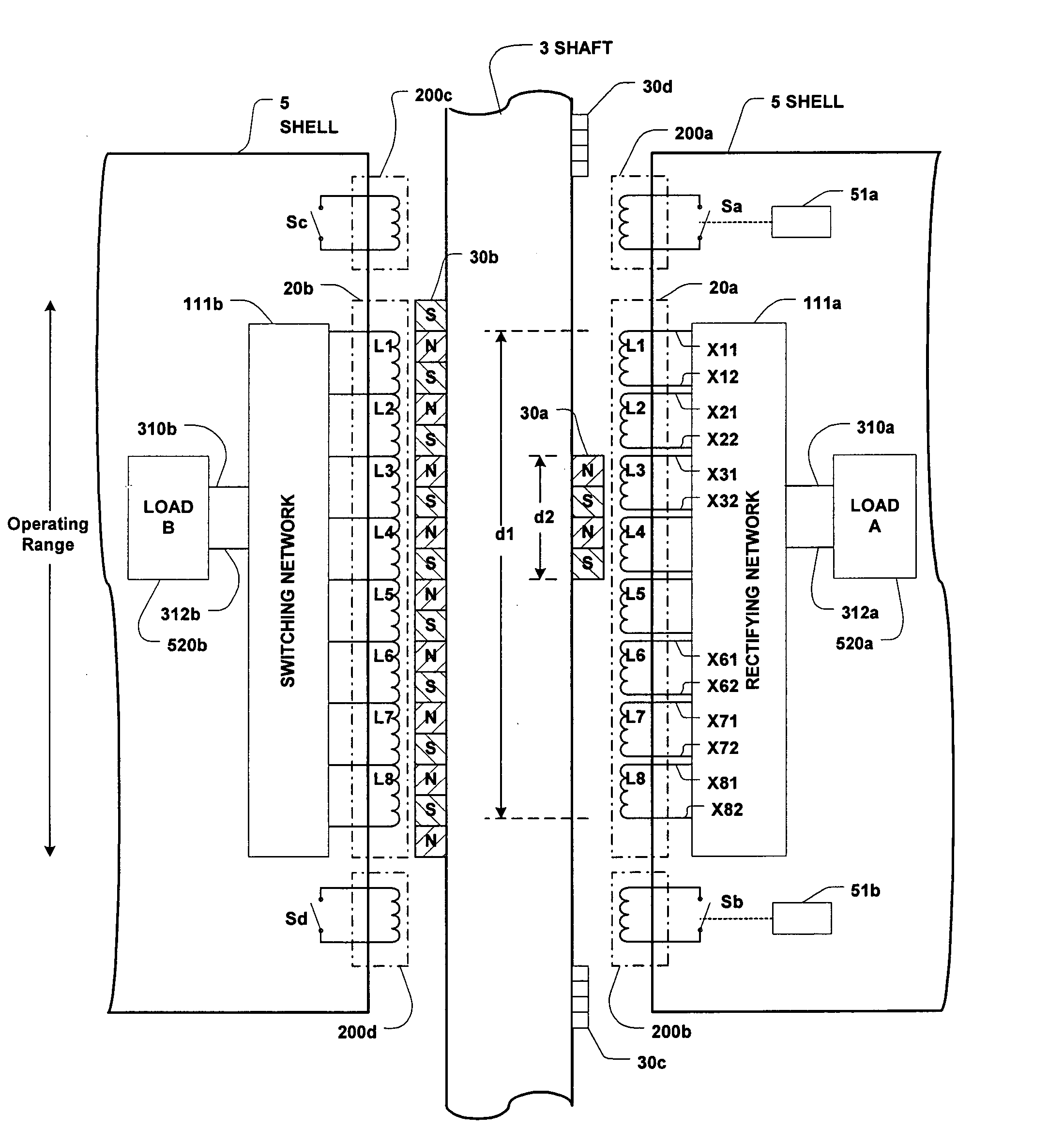
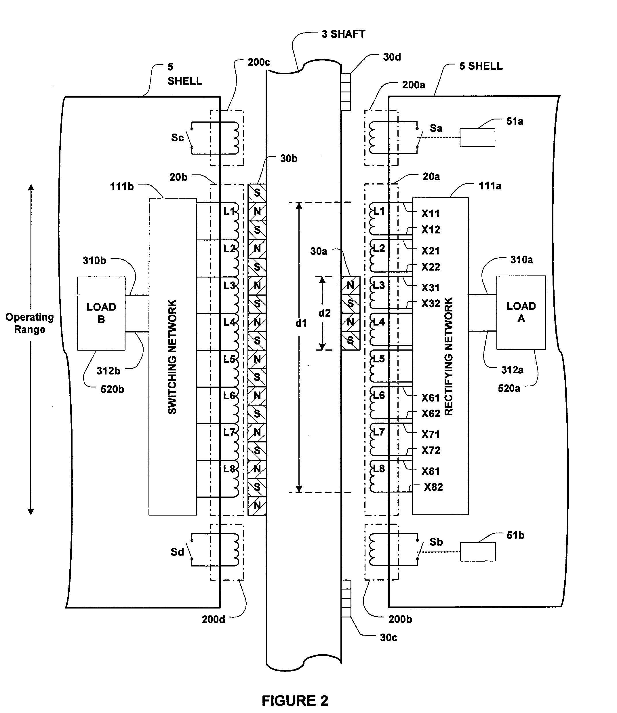
[0027] Referring to FIG. 2, there is shown a column 3 and a shell 5 of a wave energy converter (WEC) which may be, for example, of the type shown in FIGS. 11A, 11B, 11C and 11D and / or of any other suitable configuration. A permanent magnetic assembly (PMA) 30a is mounted on, and attached to, one side of column 3, and an induction coil assembly (ICA) 20a is mounted on, and attached to, the float 5 opposite PMA30a. As the float 5 moves relative to the column 3 over a range defined as the “operating range”, (see FIG. 1) output voltages are produced across ICA 20a. These voltages are fed to a power converter (shown to include a rectifying network 111a and a load 520a) to produce useful system voltage and current (power) output. Thus, PMA 30a and ICA 20a function as the basic elements of the power take-off (PTO) circuitry.

[0028] The PTO may also include a PMA 30b (which is shown to be much longer than 30a) and an induction coil assembly (ICA) 20b which may be of similar size to, or smal...


PUM

PropertyMeasurementUnit
Magnetic fieldaaaaaaaaaa
Energyaaaaaaaaaa
Displacementaaaaaaaaaa

Abstract

A magnetic braking system for inhibiting excessive motion between a float and a column intended to be placed in a body of water; with the float and column moving relative to each other as a function of the waves present in the body of water. The braking system includes a permanent magnetic assembly (PMA) mounted on, and attached to, one of the float and column and a coil assembly (or a conductive plate) mounted on, and attached to, the other one of the float and column. The braking system is mounted such that motion between the float and the column is inhibited when the displacement of the float relative to the column exceeds a predetermined operating range.

Description

CROSS REFERENCES TO RELATED APPLICATIONS [0001] This application claims priority from provisional patent application Ser. No. 60 / 553,666 titled Wave Energy Converters (WECs) with Linear Electric Generators (LEGs) filed Mar. 16, 2004, the teachings of which are incorporated herein by reference.BACKGROUND OF THE INVENTION [0002] This invention relates to apparatus and methods for inhibiting excessive motion between selected moving components of a wave energy converter (WEC). Known wave energy converters (WECs) include two basic components which, when placed in a body of water, are designed to move relative to each other, in response to the motion of ocean (sea) waves. One of the two components may be denoted as a “float” (or shell) and the other one of the two components may be denoted as a central “column” (shaft or spar). A power take off (PTO) device is connected between the two components to convert their relative motion into electric energy. [0003] A problem faced by the Applican...

Claims


Application Information

Patent Timeline
IPC IPC(8): A01D75/30C12N9/42F03B13/18F03B13/20F03B15/00F03C1/00H02K7/18H02K35/02
CPCB60L7/003H02P25/18F03B13/20F05B2220/7068F05B2220/707F05B2260/50F05B2260/903H02K7/1876H02K35/02H02P3/22Y02E10/38Y02T10/641Y02T10/642H02P9/008F03B13/1845Y02P60/12H02K35/04H02K7/106Y02E10/30Y02T10/64
Inventor STEWART, DAVID B.TAYLOR, GEORGE W.
Owner OCEAN POWER TECHNOLOGIES
Learn More