Apparatus carrying a mounted RFID circuit for the purpose of deploying and generating a tracking signal (post shot only) from an arrow

Inactive Publication Date: 2005-10-20
PRIDMORE CHARLES FRANKLIN JR +1
View PDF12 Cites 23 Cited by
  • Summary
  • Abstract
  • Description
  • Claims
  • Application Information

AI Technical Summary

Benefits of technology

[0014] Another object of the invention is In accordance with a preferred embodiment of the invention, there is disclosed an apparatus (Arrow mounted RFID Carrier) for the purpose of generating a tracking signal from a deployed hunting broad head arrow, comprised of a plastic carrier that is universal to the modern hunting broad head configurations currently on the market. Self contained RFID Electronics which consist of RFID Chip, battery, antenna. This apparatus does not negatively impact arrow / broad head performance, and this apparatus deploys RFID Technology in the field that will assist in the successful recovery of harvested game animals.

Problems solved by technology

During over 60 years of personal hunting experience by the inventors, they have been exposed to the disappointment in lost trophy's due to ineffective marksmanship, impossible terrain and weather conditions or a combination of multiples of these listed issues.
Earlier Technologies were prohibitive based upon size issue with the RFID Chip technology.

Method used


Image

  • Apparatus carrying a mounted RFID circuit for the purpose of deploying and generating a tracking signal (post shot only) from an arrow
  • Apparatus carrying a mounted RFID circuit for the purpose of deploying and generating a tracking signal (post shot only) from an arrow
  • Apparatus carrying a mounted RFID circuit for the purpose of deploying and generating a tracking signal (post shot only) from an arrow

Examples


Embodiment Construction

[0021] Detailed descriptions of the preferred embodiment are provided herein. It is to be understood, however, that the present invention may be embodied in various forms. Therefore, specific details disclosed herein are not to be interpreted as limiting, but rather as a basis for the claims and as a representative basis for teaching one skilled in the art to employ the present invention in virtually any appropriately detailed system, structure or manner.

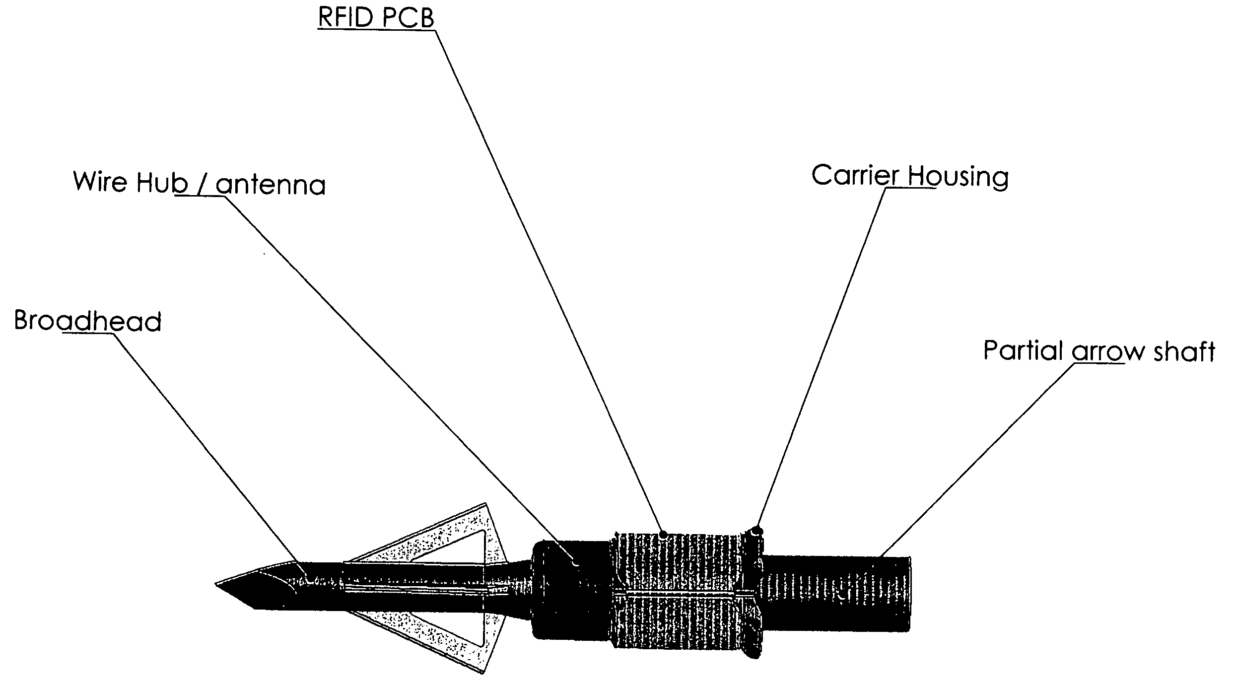
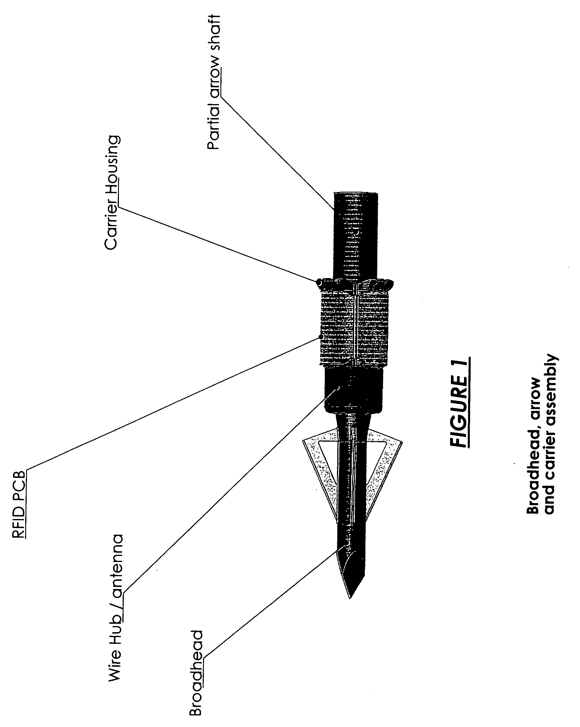
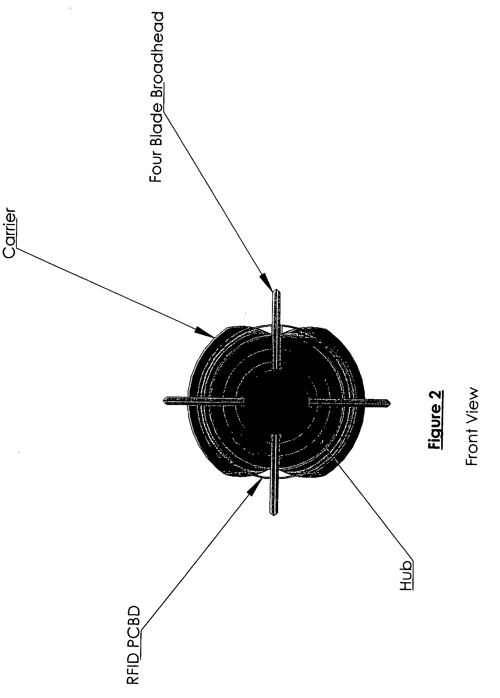
[0022] Turning first to FIG. 1 here is shown the invention assembly known here in as the Arrow Mounted RFID Carrier. This assembly is the housing of the carrier for the RFID Electronics and the supporting components. This is also the deployment platform for the RFID Electronics. The assembly components are to be constructed of a molded material or of light gauge wire (38 AWG or thinner) and pcbd substrate, be light weight, aerodynamic and will not impede the performance of the broad head or arrow. The front tip of the carrier is ta...


PUM


Abstract

This invention utilizes RFID Technology, plastic injection molded components, a flexible PCB, Micro batteries, active and passive electronic components and antenna wire to form an apparatus (Arrow mounted RFID Carrier) for the purpose of deploying and generating a tracking signal from an arrow mounted RFID Circuit. This device is mounted to the arrow shaft (no special tooling required) and is deployed upon impact with the target. During impact the Carrier assembly opens and separates from the arrow shaft and the antenna wire deploys to a given length, one end of the antenna wire penetrating the target and exiting the opposite side of the target while the trailing end remains exterior to the entry side of the broad head impact surface. Mean while, PCB Mounted components, IE Batteries, saline sensor, RFID Chip, etc, are activated by internal contact with body tissues and begin to emit a low level signal through the antenna wire which is then received by a hand held reader device. Distances of signal sensitivity are impacted by environmental conditions and life cycle of pulses can be limited, preferably to less than 24 hours by adjusting the power draw on the batteries.

Description

CROSS REFERENCE TO RELATED APPLICATIONS [0001] This is a continuation in part of Ser. No. 60 / 563,000, filed on Apr. 19, 2004 and Ser. No. 60 / 612,147 filed on Sep. 23, 2004STATEMENT REGARDING FEDERALLY SPONSORED RESEARCH OR DEVELOPMENT [0002] Not Applicable DESCRIPTION OF ATTACHED APPENDIX [0003] Not Applicable BACKGROUND OF THE INVENTION [0004] This invention relates generally to the field of RFID Technology and more specifically to an apparatus (Arrow mounted RFID Carrier) for the purpose of deploying and generating a tracking signal from an arrow mounted RFID Circuit. [0005] Since May 2003 Charles F. Pridmore Jr. and Peter G. Babendreier (Inventors) have been developing the listed apparatus for use by bow hunting sportsmen. This device takes elements of RFID Technology and incorporates it into a deployable carrier which will help to eliminate wasted game by assisting both experienced and novice sportsmen in tracking targeted and struck game animals. During over 60 years of persona...

Claims


Application Information

Patent Timeline
IPC IPC(8): A01M31/00F42B12/38G08B1/08
CPCF42B12/385A01M31/002
Inventor PRIDMORE, CHARLES FRANKLIN JR.BABENDREIER, PETER
Owner PRIDMORE CHARLES FRANKLIN JR
Why Eureka
Try Eureka