Motion blur correction

a correction and motion blur technology, applied in the field of image processing, can solve the problems of general usefulness, direction estimation technique, and well-known motion blur problems, and achieve the effects of avoiding the effect of ringing, reducing the likelihood of declaring an inaccurate blur direction, and reducing unnecessary correction and overcorrection

Inactive Publication Date: 2005-10-20
SEIKO EPSON CORP
View PDF11 Cites 117 Cited by
  • Summary
  • Abstract
  • Description
  • Claims
  • Application Information

AI Technical Summary

Benefits of technology

[0017] According to one aspect of the present invention, there is provided a method of correcting blur in a motion blurred image using an estimate of motion blur direction and motion blur extent based on the motion blurred image. During the method, an initial guess image is generated based on the motion blurred image. The guess image is blurred as a function of the estimated blur direction and blur extent. The blurred guess image is compared with the motion blurred image to generate an error image. The error image is blurred and weighted and combined with the initial guess image thereby to update the guess image and correct for blur.
[0023] According to still yet another aspect of the present invention, there is provided an apparatus for correcting blur in a motion blurred image using an estimate of motion blur direction and motion blur extent based on the motion blur image. The apparatus includes a motion blur filter blurring an initial guess image based on the motion blurred image as a function of the estimated blur direction and blur extent. A comparator compares the blurred guess image with the motion blurred image and generates an error image. The motion blur filter further blurs the error image and weights the error image according to an error weighting factor. An adder combines the error image and the initial guess image thereby to update the guess image and correct for blur.
[0024] The present invention provides advantages in that since the total edge response over all of the discrete directions and over subgroups of the discrete directions are taken into account during blur direction determination, undesirable effects due to anomalies in a particular direction resulting from noise and / or insufficient edge information are dampened. As a result, the likelihood of declaring an inaccurate blur direction is significantly reduced as compared to prior art blur direction estimation techniques.
[0025] The present invention also provides advantages in that since blur correction is weighted using a factor that is based on blur direction, unnecessary correction and overcorrection is reduced thereby to avoid the effects of ringing.

Problems solved by technology

Motion blur is a well-known problem in the imaging art that may occur during image capture using digital video or still-photo cameras.
This blur direction estimation technique unfortunately suffers disadvantages in that it is useful generally only in situations where sufficient edge information is available in each of the measured directions.
For instance, this blur direction estimation technique may incorrectly declare the measured direction having the lowest intensity after high-pass filtering to be the blur direction in the situation where the low intensity is a result of scarce edge information in the original, unblurred image and not due to blur.
Furthermore, this blur direction estimation technique is very sensitive to errors due to noise, which may in any particular direction tend to either sharpen or soften edges.
Unfortunately, the Biemond et al. blur correction technique suffers disadvantages.
Convolving the blurred image with the inverse of the motion blur filter can lead to excessive noise magnification.
Furthermore, with reference to the restoration equation disclosed by Biemond et al., the error contributing term having positive spikes at integer multiples of the blurring distance is amplified when convolved with high contrast structures such as edges in the blurred image, leading to undesirable ringing.
However, with this approach, ringing noise may still remain in local regions containing edges.
While iterative methods such as that described above provide some advantage over direct reversal of blur using motion blur filters, these known iterative methods are still often subject to overcorrection in some areas of the image, leading to non-uniform results and significant ringing.

Method used


Image

  • Motion blur correction
  • Motion blur correction
  • Motion blur correction

Examples


Embodiment Construction

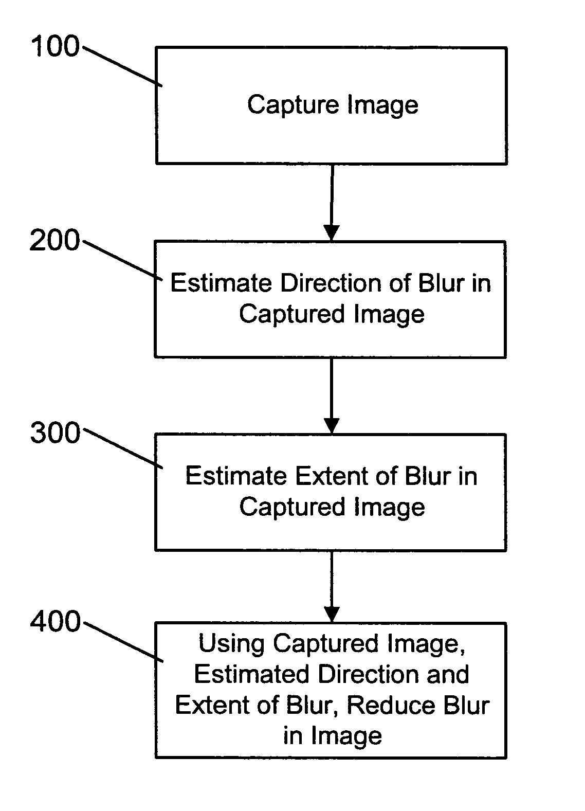
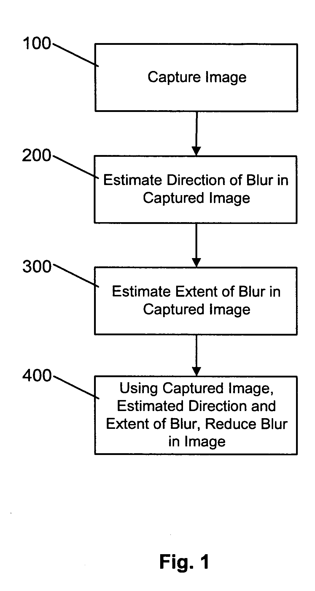
[0037] Turning now to FIG. 1, a method of correcting motion blur in an image captured by a digital camera, digital video camera or the like is shown. During the method, when a motion blurred image is captured (step 100), the direction of blur in the captured image is initially estimated using edge information in the captured image (step 200). Once the blur direction is estimated, the extent of blur in the captured image is estimated using a correlation-based technique (step 300). With the estimated motion blur parameters (i.e. the estimated blur direction and blur extent) determined, the estimated motion blur parameters are used to reduce motion blur in the captured image (step 400) thereby to generate a motion blur corrected image.

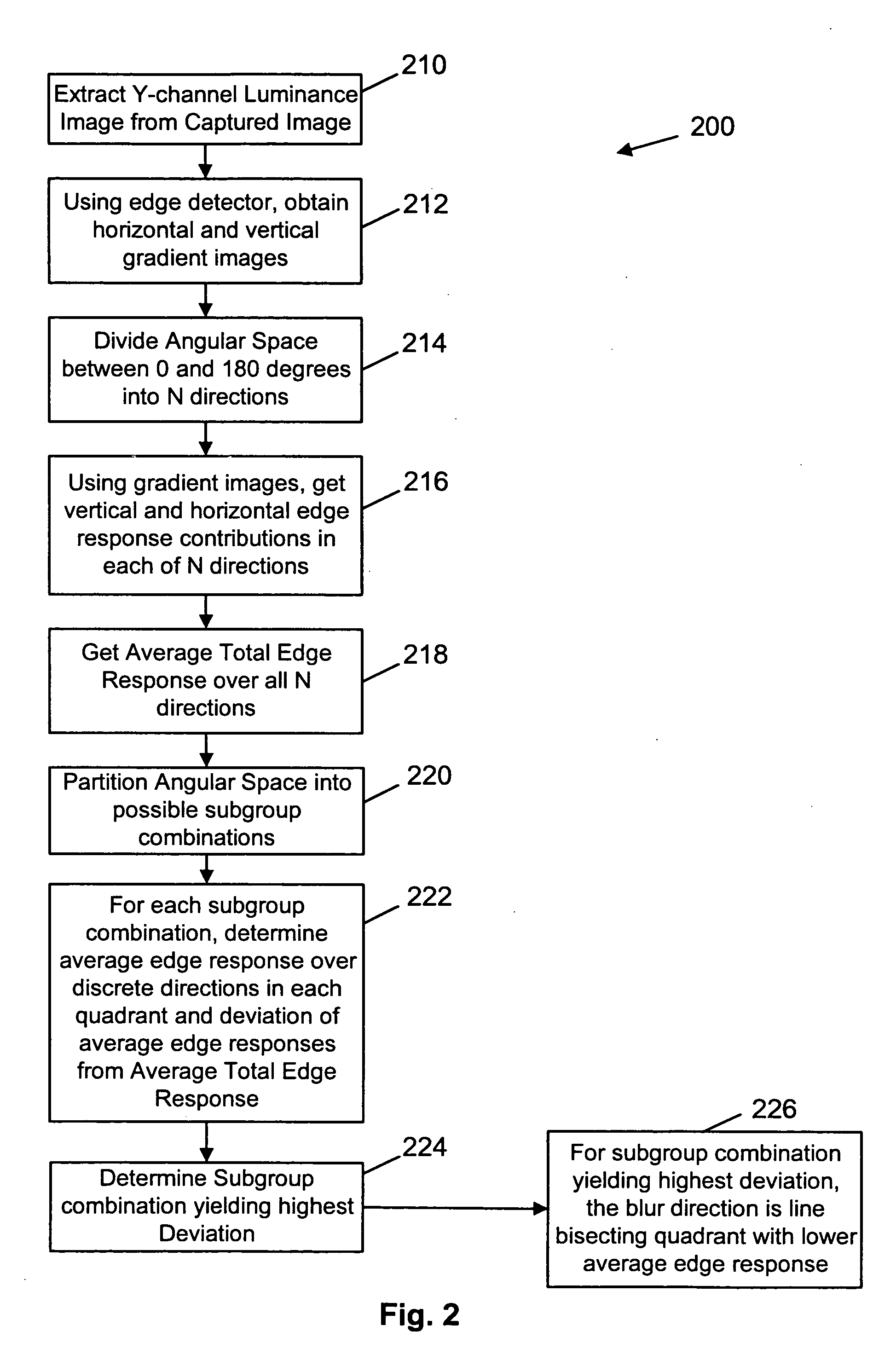
[0038]FIG. 2 illustrates the steps performed during blur direction estimation (step 200). Initially, a Y-channel luminance image is extracted from the captured motion blurred image (step 210). The extracted image is then convolved with a Sobel edge detec...


PUM


Abstract

A method and apparatus of correcting blur in a motion blurred image includes estimating the direction of blur in the motion blurred image based on edge response of the motion blurred image over a set of discrete directions and over subgroups of the discrete directions. The extent of blur in the motion blurred image is also estimated. An initial guess image based on the motion blurred image is generated and the guess image is blurred as a function of the estimated blur direction and blur extent. The blurred guess image is compared with the motion blurred image to generate an error image. The error image is blurred and weighted and then combined with the initial guess image thereby to update the guess image and correct for blur.

Description

FIELD OF THE INVENTION [0001] The present invention relates generally to image processing, and more particularly to a method and apparatus for reducing motion blur in an image and to a method and apparatus for estimating blur direction in a motion blurred image. BACKGROUND OF THE INVENTION [0002] Motion blur is a well-known problem in the imaging art that may occur during image capture using digital video or still-photo cameras. Motion blur is caused by camera motion, such as vibration, during the image capture process. It is somewhat rare to have a priori measurements of actual camera motion when motion blur occurs and as such, techniques have been developed to correct for motion blur in captured images. [0003] For example, blind motion blur correction is a known technique for correcting motion blur in captured images. This technique corrects motion blur based on attributes intrinsic to the captured motion blurred image. Blind motion blur correction seeks to estimate camera motion ...

Claims


Application Information

Patent Timeline
Patent Type & Authority Applications(United States)
IPC IPC(8): G06T5/00G06T7/20G06T5/50G06T7/60
CPCG06T2207/20201G06T5/004
Inventor POON, EUNICE
Owner SEIKO EPSON CORP
Why Eureka
Try Eureka