Pressurized reactor apparatus with magnetic stirring

a pressurized reactor and magnetic stirring technology, applied in the field of single or parallel research reactors, can solve the problems of inability to perform high temperature reactions, inability to stir high viscosity reaction mixtures, and system processing typically not capable of being elevated temperatures

Inactive Publication Date: 2005-10-20
FREESLATE
View PDF24 Cites 50 Cited by
  • Summary
  • Abstract
  • Description
  • Claims
  • Application Information

AI Technical Summary

Problems solved by technology

Many prior art processing systems use magnetically coupled stirring, but such systems typically are not capable of processing at elevated temperatures, such as those up to 350° C.
Such stirring elements are not capable of performing in high temperature reactions because the non-metallic coating is not capable of maintaining its structural integrity at elevated temperatures.
Such stirrers are capable of basic mixing of a reaction mixture, but are not capable of stirring highly viscous reaction mixtures, or those reaction mixtures requiring a specific type of stirrer, such as a high shear stirrer.
Moreover, such stirrers are generally confined to the lower portion of the reaction vessel, which may limit their ability to stir the entire reaction mixture.
Such devices suffer from various drawbacks, including increased headspace above the reaction mixture and increased wettable surface area within the reaction chamber.
Such designs provide effective stirring because they are shaft driven, but the increased wettable surface area increases the likelihood of condensation within the reaction chamber, which removes materials from the reaction mixture, thereby potentially altering its chemical composition, which may alter the results of the experiment.
Dynamic seals are more difficult to maintain and are less capable of performing at elevated temperatures.
Moreover, these systems require an additional seal for each reactor, thereby increasing the likelihood of leaks and pressure losses due to improper sealing.
Previous reactor systems lack these capabilities.

Method used


Image

  • Pressurized reactor apparatus with magnetic stirring
  • Pressurized reactor apparatus with magnetic stirring
  • Pressurized reactor apparatus with magnetic stirring

Examples


Embodiment Construction

Reactor Module Overview

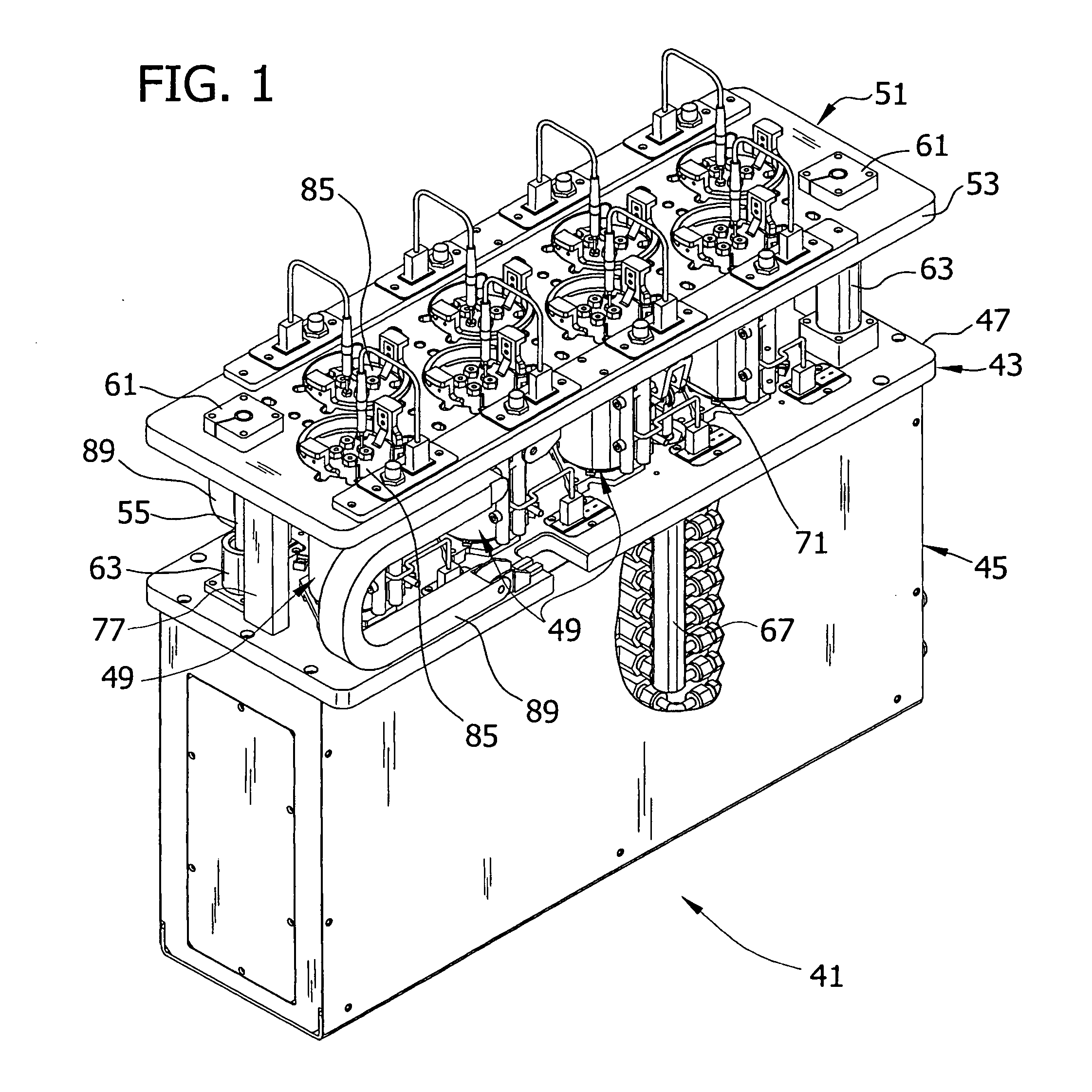
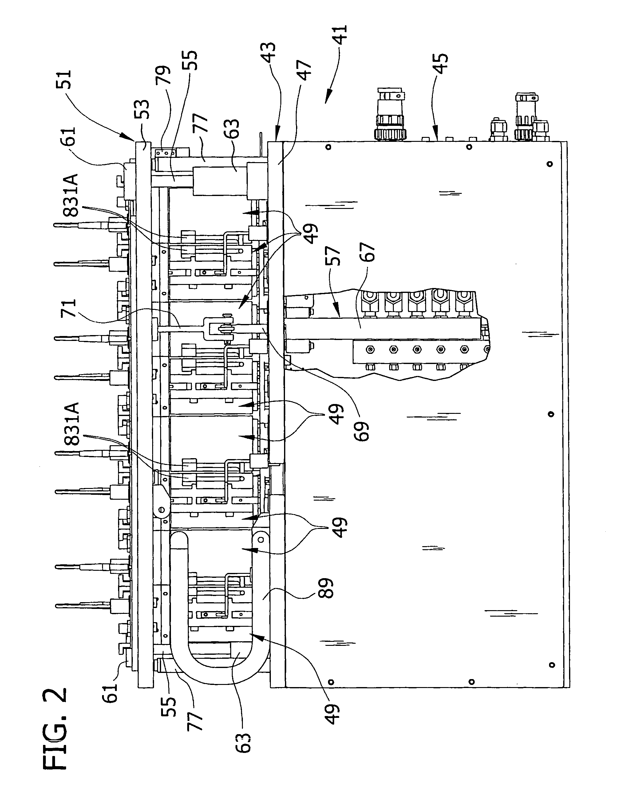
[0062] Referring now to the drawings and specifically FIGS. 1 and 2, apparatus for parallel processing of reaction mixtures is indicated in its entirety by the reference numeral 41. As used herein, in the context of methodology, the term “parallel” means that two or more of the multiple reaction mixtures are processed either simultaneously or at least during overlapping time periods. In the context of apparatus 41, the term parallel means that the apparatus is integrated structurally or through software (e.g., control software) and is adapted for effecting reactions in two or more reaction vessels simultaneously or at least during overlapping time periods. The apparatus 41, which may be referred to as a parallel reactor system, is similar in certain respects to the parallel reactor system described in the aforementioned publications and applications, including U.S. application Ser. No. 09 / 548,848, filed Apr. 13, 2000, now U.S. Pat. No. 6,455,316, issued Sep....


PUM

PropertyMeasurementUnit
included angleaaaaaaaaaa
temperaturesaaaaaaaaaa
total volumeaaaaaaaaaa

Abstract

An apparatus for parallel processing of reaction mixtures comprises a plurality of vessels for holding a plurality of reaction mixtures for processing. A plurality of vessel supports are adapted for supporting the plurality of vessels. Caps sealingly engage the vessel supports for sealing the vessels within the vessel supports. The vessels, vessel supports, and caps define reaction chambers having bearings and stirrers rotatable therein. The stirrers each comprise a spindle rotatable in a respective bearing and at least one stirring implement extending from the spindle for contacting a respective reaction mixture. The stirrers further comprise at least one magnet adapted to be subjected to a rotating magnetic field in the vessel for causing the stirrer to rotate thereby to mix the respective reaction mixture. The stirrers may further comprise a first magnetic follower, a second magnetic follower, and a flux guide for guiding magnetic flux between the first magnetic follower and the second magnetic follower, thereby creating a magnetic flux path between the stirrer and a respective one of a plurality of magnetic drivers coupled to the stirrers for rotating the stirrers within the vessels.

Description

BACKGROUND OF THE INVENTION [0001] The present invention relates generally to reactors, and in particular, to single or parallel research reactors suitable for use in a combinatorial (i.e., high-throughput) science research program in which chemical reactions are conducted simultaneously using small volumes of reaction materials to efficiently and economically screen large libraries of chemical materials. [0002] Reactors of this type are disclosed in co-owned International Application No. PCT / US 99 / 18358, filed Aug. 12, 1999, by Turner et al., entitled Parallel Reactor with Internal Sensing and Method of Using Same, published Feb. 24, 2000 (International Publication No. WO 00 / 09255), which is incorporated herein by reference for all purposes. This PCT application claims priority from the following co-owned, U.S. applications bearing the same title, all of which are also incorporated by reference for all purposes: U.S. application Ser. No. 09 / 211,982, filed Dec. 14, 1998, by Turner e...

Claims


Application Information

Patent Timeline
Patent Type & Authority Applications(United States)
IPC IPC(8): B01F1/00B01F7/00B01F7/24B01F13/08B01F13/10B01F15/00B01J19/00
CPCB01F7/00166B01F7/00033B01F13/0827B01F13/1013B01F13/1022B01J19/0046B01J2219/00283B01J2219/00308B01J2219/00344B01J2219/00389B01J2219/00477B01J2219/00481B01J2219/00495B01J2219/00585B01J2219/00599B01J2219/00689B01J2219/00691B01J2219/00698B01F7/24B01F27/053B01F27/07261B01F27/92B01F33/4534B01F33/81B01F33/813B01F33/453
Inventor HIGASHIHARA, KENNETH S.SAXTON, ROBERT J.WELLS, JASON
Owner FREESLATE
Why Eureka
Try Eureka