
Microphone

Inactive Publication Date: 2005-10-20
AUDIO-TECHNICA
View PDF3 Cites 51 Cited by
  • Summary
  • Abstract
  • Description
  • Claims
  • Application Information

AI Technical Summary

Benefits of technology

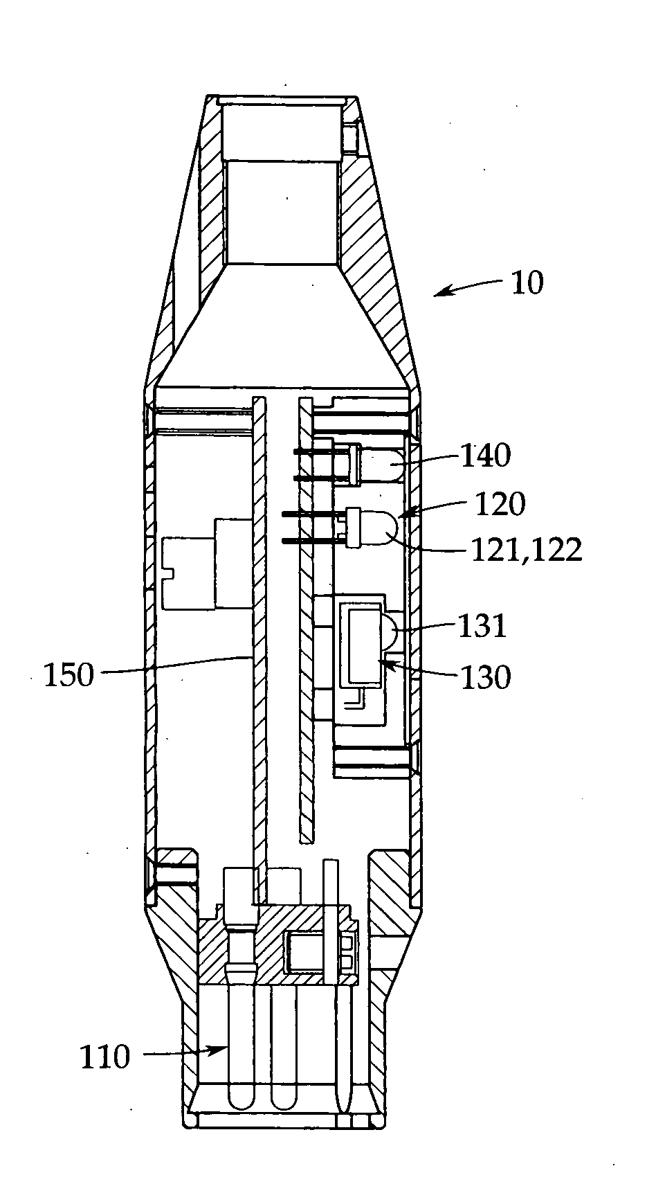
[0009] It is thus an object of the present invention to provide a microphone which uses an infrared light emitting element and an infrared light receiving element as a proximity sensor and which can reliably sense a person (speaker) by avoiding the adverse effect of disturbing light without the need for a special optical filter.
[0013] According to the present invention, the infrared light receiving element has a particular tuning frequency. The infrared light emitting element radiates infrared rays at the tuning frequency. Accordingly, the infrared light receiving element outputs a light reception signal (person sensing signal) only if light radiated by the infrared light emitting element and reflected by a person (speaker) is incident on the infrared light receiving element. This serves to provide a microphone having a proximity sensor that is inexpensive because it eliminates the need for a special, expensive optical filter and that does not malfunction even with disturbing light.

Problems solved by technology

The phantom power source does not have an excellent current supply capability, so that the proximity sensor needs to consume reduced power.
However, when a person (speaker) is stationary, the sensor does not sense the person.
However, if external light such as sunlight enters the room or there is, for example, a plasma display nearby, which may generate harmonics of infrared rays, this may cause the elements to malfunction.
This kind of optical filter is relatively expensive.
The ultrasonic sensor consumes a large amount of power and provides sound waves that may be diffracted by surrounding objects.
Therefore, the ultrasonic sensor is not reliable in sensing and is not applicable to microphones.

Method used


Image

  • Microphone
  • Microphone
  • Microphone

Examples


Embodiment Construction

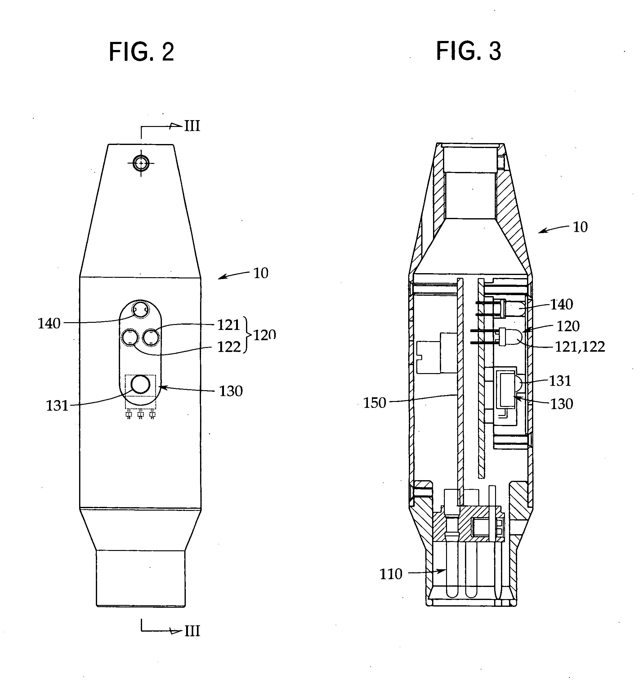
[0020] An embodiment of the present invention will be described with reference to FIGS. 1 to 6. However, the present invention is not limited to this.

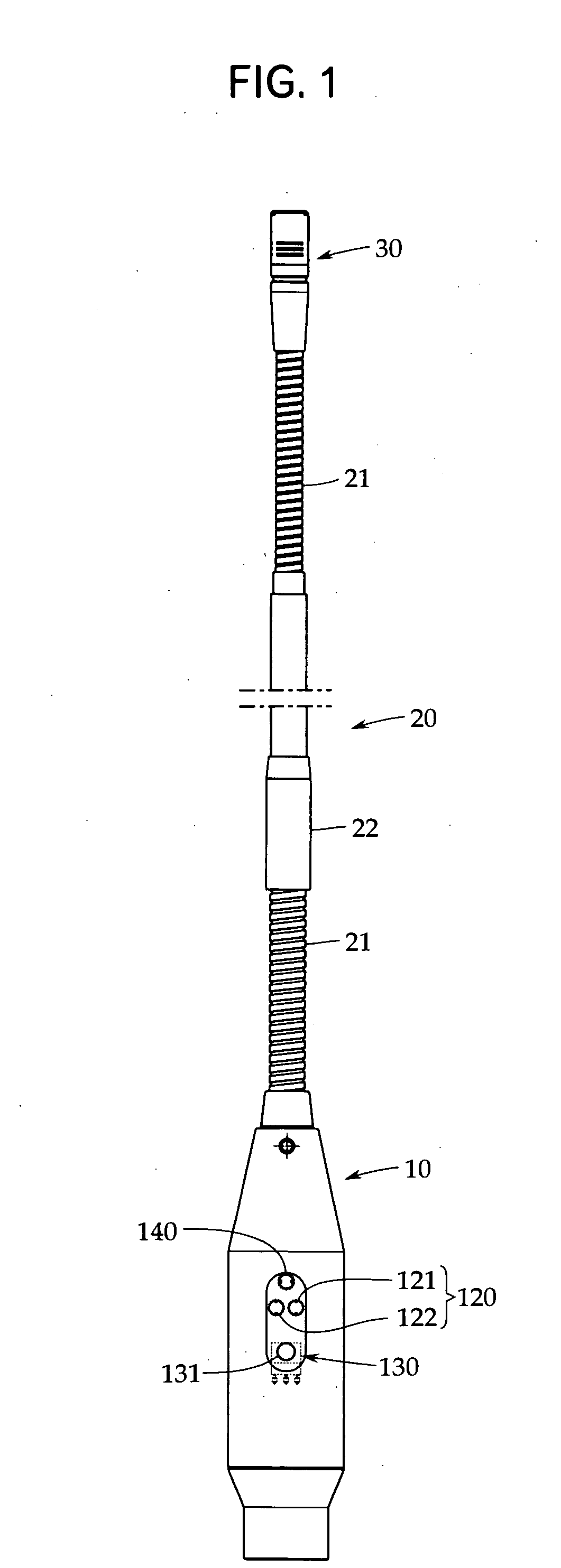
[0021]FIG. 1 shows the appearance of a microphone according to a preferred aspect of the present invention; the microphone is of a goose neck type. The microphone is assumed to be installed on a base such as a table which is not shown in the drawings. Accordingly, the microphone comprises a cylindrical base housing 10 connected to a predetermined fixture provided on the base. The base housing 10 needs to shield incorporated parts from external electromagnetic waves. Thus, the base housing 10 is preferably made of a metal material such as brass.

[0022] In this example, a lower end of a flexible support shaft 20 is fixed to an upper end of the base housing 10; the support shaft 20 includes a flexible shaft 21 and a nested telescopic pipe 22. The flexible shaft 21 and the nested telescopic pipe 22 are made of metal. The support shaft 20 ...


PUM


Abstract

A microphone uses an infrared light emitting element and an infrared light receiving element as a proximity sensor. The microphone can avoid the adverse effect of disturbing light without the need for a special optical filter to enable a person (speaker) to be reliably sensed. The microphone includes a microphone unit which converts a sound wave into an electric signal to output the signal from a microphone output section 151, and a proximity sensor. An output signal from the proximity sensor controllably turns on and off the microphone output section 151. The proximity sensor includes an infrared light receiving element 131 tuned only to a particular frequency to output a light reception signal and infrared light emitting elements 121 and 122 which emit infrared rays at the frequency to which the infrared light receiving element is tuned.

Description

FIELD OF THE INVENTION [0001] The present invention relates to a microphone, and more specifically, to a microphone comprising a function for turning on and off a microphone output using a proximity sensor. BACKGROUND ART [0002] Some microphones incorporate a proximity sensor. These microphones use the proximity sensor to sense whether or not there is a person in proximity to the microphone. When the sensor senses a person, it turns on the microphone output. When the sensor does not sense any person, it turns off the microphone output. [0003] For example, such a microphone is used in a church having no microphone operator. That is, in such a church a goose neck microphone is set on a platform. If a clergyman is on the platform to preach, the proximity sensor provides a person sense signal to turn the microphone output on. However, when the clergyman is away from the platform in order to allow a choir to sing, the sensor turns off the microphone output so as not to pick up songs of t...

Claims


Application Information

Patent Timeline
IPC IPC(8): H04R1/04H04R1/02H04R3/00H04R23/00
CPCH04R23/008
Inventor SHINOZUKA, TSURUGISASAKI, HIROKAZUAKINO, HIROSHI
Owner AUDIO-TECHNICA
Learn More