Method and apparatus for measuring frequency-resolved states of polarization of a working optical channel using polarization-scrambled heterodyning

Active Publication Date: 2005-10-20
AMERICAN TELEPHONE & TELEGRAPH CO
View PDF14 Cites 13 Cited by
  • Summary
  • Abstract
  • Description
  • Claims
  • Application Information

AI Technical Summary

Benefits of technology

[0006] The present invention, which addresses the needs unmet by conventional methods, relates to a meth

Problems solved by technology

Consequently, different polarization components of an optical signal will propagate at different velocities, resulting in a differential group delay (DGD) between the components, and causing significant broadening of the optical pulses propagating along long lengths of fiber.
PMD is widely recognized as a potential limiting factor in high-speed optical

Method used


Image

  • Method and apparatus for measuring frequency-resolved states of polarization of a working optical channel using polarization-scrambled heterodyning
  • Method and apparatus for measuring frequency-resolved states of polarization of a working optical channel using polarization-scrambled heterodyning
  • Method and apparatus for measuring frequency-resolved states of polarization of a working optical channel using polarization-scrambled heterodyning

Examples


Embodiment Construction

[0030] The “states of polarization” may be any set of vectors and corresponding vector coefficients which can be used to completely characterize the polarization state of an optical wave or signal. As is well-known to those skilled in the art, the states of polarization are characterized by the three-component Stokes vector derived from the four Stokes parameters. (One of the four Stokes parameters represents the total intensity in the optical wave under test, and is used to normalize the three coefficients.) Also well-known to those skilled in the art, the Stokes vectors are the unit vectors on the so-called “Poincaré sphere” used to describe the polarization of an optical wave or signal.

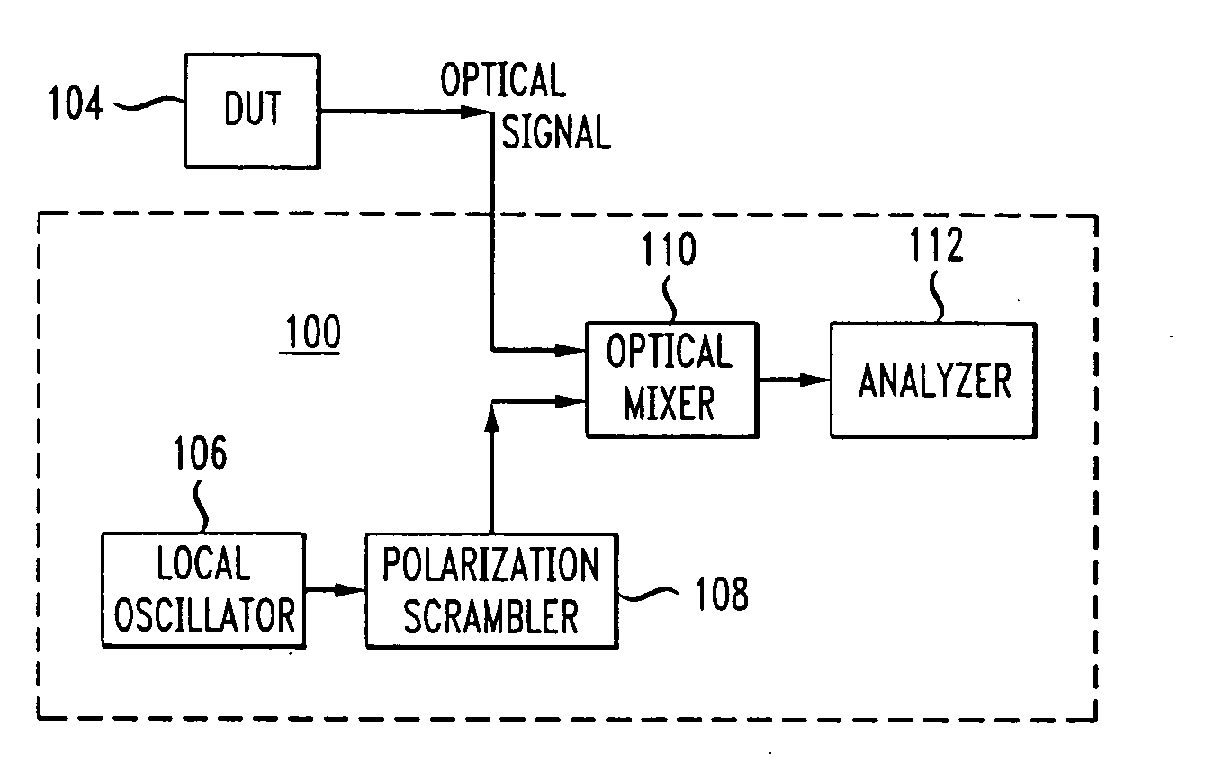
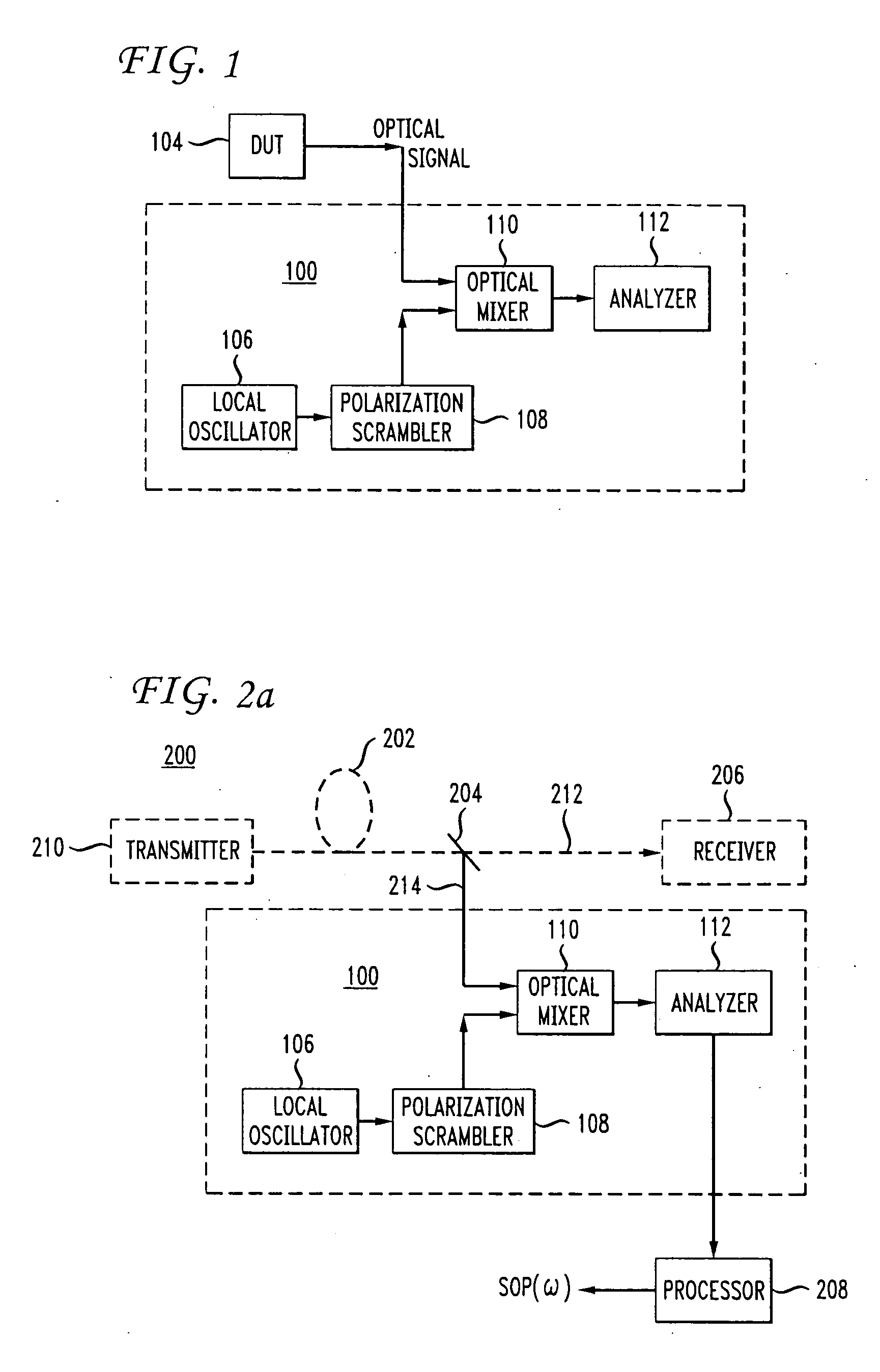
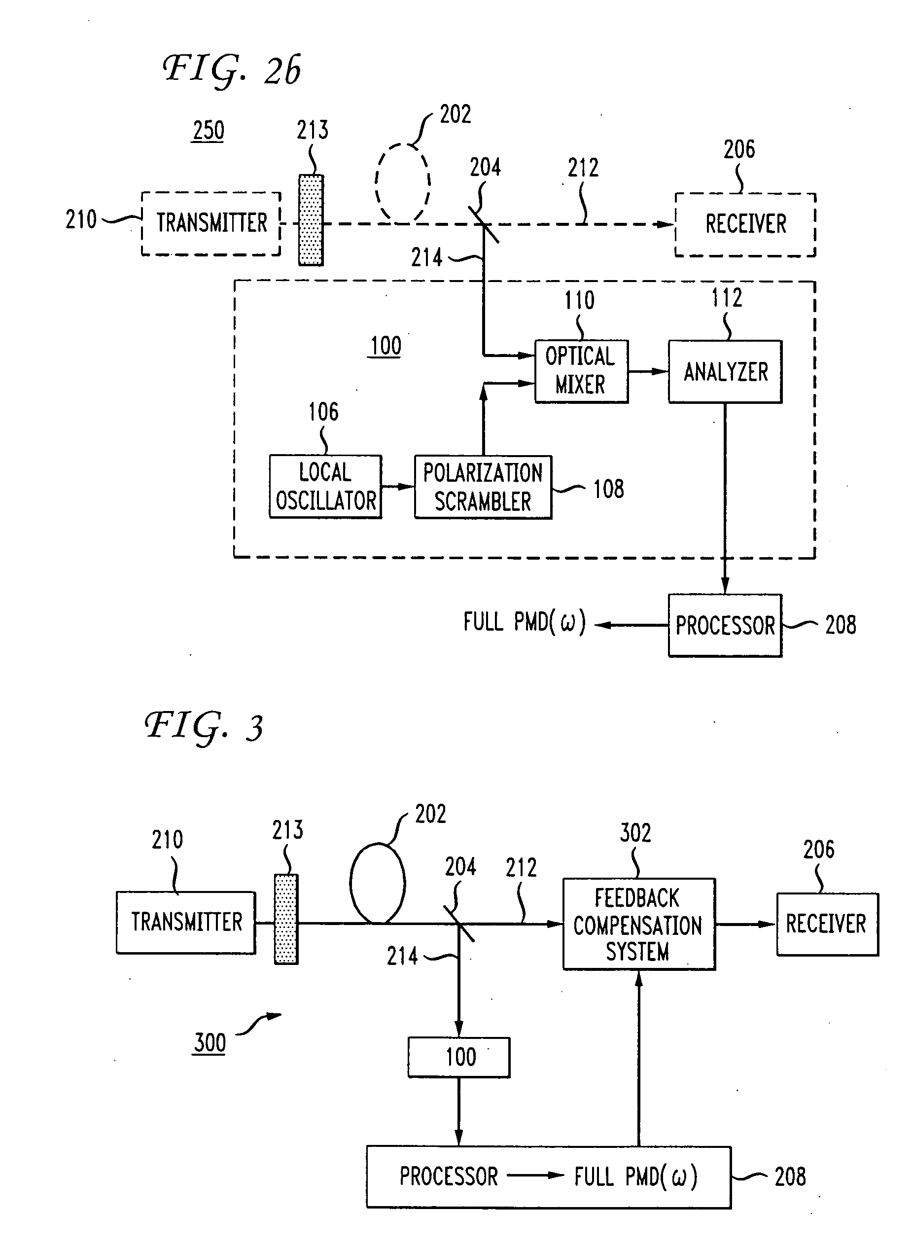
[0031] In optical telecommunication networks, multiple working optical channels are typically carried on a single optical fiber. The single optical fiber is included in an optical fiber link, which includes the optical fiber and optical amplifiers and any other optical components between two conne...


PUM


Abstract

An apparatus for measuring a set of frequency-resolved states of polarization (SOP) of an optical signal includes a local oscillator (LO), a polarization scrambler, a coupler for mixing the polarization-scrambled signal with the optical signal to produce a heterodyned signal with a radio frequency (RF) component, and an analyzer for passing a fixed polarization component and resolving the polarization and frequency from the RF component. The apparatus is used for measuring, monitoring or compensating the polarization mode dispersion (PMD) in a working channel of an optical telecommunication system. A method for measuring frequency-resolved SOP of an optical signal includes tuning and polarization-scrambling a local oscillator (LO), mixing the scrambled LO with the optical signal, and resolving the RF signal in frequency and polarization. The method is applied to measure and monitor PMD in a working optical channel, and to dynamically compensate for the PMD.

Description

FIELD OF THE INVENTION [0001] The invention relates to the field of high-speed optical telecommunication systems, and more particularly to a method and apparatus for measuring the frequency-resolved states of polarization of a working optical telecommunication channel. BACKGROUND OF THE INVENTION [0002] The optical waveguides or fibers used to transmit signals in optical telecommunication systems are characterized, in part, by the vector property of polarization mode dispersion (PMD). Polarization mode dispersion occurs as a result of birefringence in the fiber, which may be caused by physical asymmetry in the fiber construction itself, or by stress, strain, or other external forces imposed on the fiber. Optical fibers display an anisotropy in the refractive index, which will vary as a function of position along the fiber and as a function of time. In addition, random polarization coupling can occur, giving rise to time-varying birefringence statistics. Consequently, different polar...

Claims


Application Information

Patent Timeline
IPC IPC(8): H04B10/04H04B10/02H04B10/06H04B10/08H04B10/142H04B10/148H04B10/152H04B10/18
CPCH04B10/07951H04B10/64H04B10/6151H04B10/2569A61H3/0244A61H2003/0272A61H2201/0161
Inventor BORODITSKY, MIKHAILBRODSKY, MIKHAILFRIGO, NICHOLAS J.MAGILL, PETER
Owner AMERICAN TELEPHONE & TELEGRAPH CO
Why Eureka
Try Eureka