Battery voltage measurement circuit

a voltage measurement and battery technology, applied in the field of battery voltage measurement circuits, can solve the problems of inability to accurately measure voltage, inability to accurately and quickly charge flying capacitors, and occurrence of leak current, however small, and achieve the effect of simplifying the calculation process and accurately and quickly measuring voltag

Active Publication Date: 2019-10-15
PANASONIC EV ENERGY CO LTD
View PDF12 Cites 0 Cited by
  • Summary
  • Abstract
  • Description
  • Claims
  • Application Information

AI Technical Summary

Benefits of technology

[0008]It is an object of the present invention to provide a battery voltage measurement circuit that accurately and quickly measures voltage with a flying capacitor even when a semiconductor switch opens and closes an electric path to the flying capacitor.
[0010]The semiconductor switch practically interrupts the circuit when deactivated but cannot prevent the flow of a small current such as leak current. Thus, even if the semiconductor switch interrupts the electric path to the capacitor, the capacitor will be charged in an unnecessary manner as time elapses however small the current may be. This will cause, for example, the problem that voltage cannot be immediately measured using the capacitor. In this regard, in the above configuration, the two terminals of the main capacitor are connected to the reference potential via the output-side semiconductor switches and the differential amplification circuits or via the input-side semiconductor switches and the external circuit. Thus, even when leak current flows through the input-side semiconductor switches or the output-side semiconductor switches, an electric path loop including the reference potential, the external detection circuit, the input-side semiconductor switches, the output-side semiconductor switches, the differential amplification circuits, and the reference potential is formed. That is, the main capacitor is not included in the electric path loop. Accordingly, when the semiconductor switch is off, even if a small current flows and time elapses, the main capacitor is not charged by the current. Thus, even if the voltages are measured in long intervals and the deactivation time of the semiconductor switch is long, the main capacitor is not charged in an unnecessary manner. This allows voltage measurement with the main capacitor to be resumed more quickly and with higher accuracy.
[0012]This configuration allows for detection of leakage from the rechargeable batteries.
[0014]This configuration allows the capacitors to have a lower withstanding voltage.
[0018]In this configuration, the difference between the output terminals of the first and second differential amplification circuit is obtained by the third differential amplification circuit. This eliminates the need for the calculation unit to calculate the difference and simplifies the calculation process. Further, even if common mode noise enters the outputs of the first and second differential amplification circuits, the common mode noise is removed when the third differential amplification circuit calculates the difference between the two outputs.
[0019]The battery voltage measurement circuit according to the aspect of the present invention accurately and quickly measures voltage with a flying capacitor even when a semiconductor switch opens and closes an electric path to the flying capacitor.

Problems solved by technology

Thus, the occurrence of leak current, however small it may be, is inevitable.
When current flows, regardless of whether the current is small like leak current, the current will cause unnecessary charging of the flying capacitor.
In such a case, the voltage may not be accurately measured.
Further, the flying capacitor may have to be discharged before measurement.

Method used


Image

  • Battery voltage measurement circuit
  • Battery voltage measurement circuit
  • Battery voltage measurement circuit

Examples


Embodiment Construction

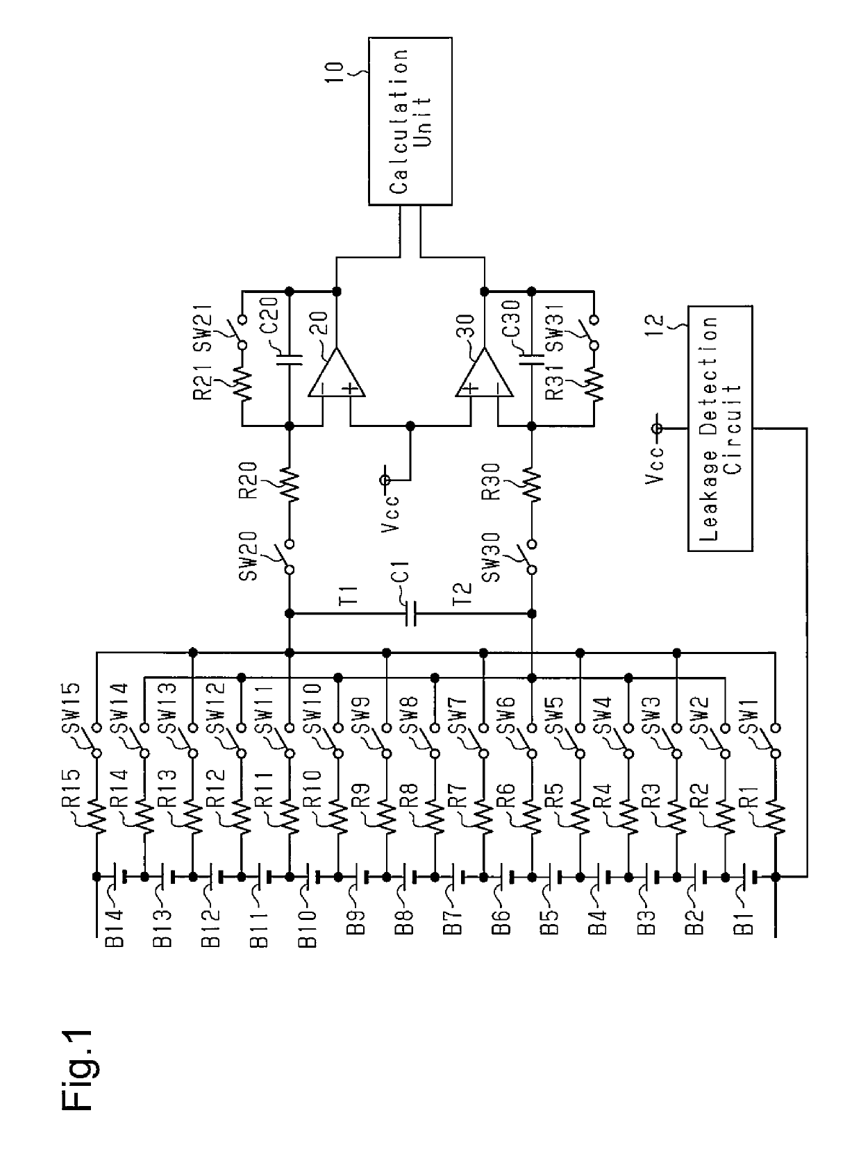
[0024]A first embodiment of a battery voltage measurement circuit will now be described with reference to FIG. 1. The battery voltage measurement circuit includes a flying capacitor voltage detection circuit and measures battery voltages at rechargeable batteries. Each rechargeable battery may be a single battery or a battery module in which a group of single batteries are connected in series. In the illustrated example, the rechargeable batteries are battery modules B1 to B14 that are connected in series to form an assembled battery. The assembled battery is installed in, for example, a vehicle such as an electric vehicle or a hybrid vehicle. Each rechargeable battery is a nickel-metal hydride rechargeable battery.

[0025]As shown in FIG. 1, a negative electrode of the assembled battery is a negative terminal of the battery module B1, and a positive electrode of the assembled battery is a positive terminal of the battery module B14. The battery modules B1 to B14 are connected to a vo...


PUM

PropertyMeasurementUnit
battery voltageaaaaaaaaaa
voltageaaaaaaaaaa
state of chargeaaaaaaaaaa

Abstract

A battery voltage measurement circuit measures voltages at a plurality of rechargeable batteries. The rechargeable batteries are connected to a flying capacitor via input-side semiconductor switches. The capacitor is connected to inverting input terminals of first and second differential amplification circuits. Output terminals of the differential amplification circuits are directly or indirectly connected to a calculation unit that calculates voltages at the rechargeable batteries. The output terminal and the inverting input terminal of each differential amplification circuit are connected via a corresponding sub-capacitor. Each differential amplification circuit includes a non-inverting input terminal connected to a reference potential. The negative electrode of the rechargeable battery is connected to the reference potential via a leakage detection circuit.

Description

TECHNICAL FIELD[0001]The present invention relates to a battery voltage measurement circuit that measures battery voltage.BACKGROUND ART[0002]Conventionally, charging and discharging of a rechargeable battery is adjusted to be performed within an appropriate range that is set based on the state of charge (SOC), which is an index indicating the charged state of the battery, to avoid excessive charging and discharging, which would deteriorate the battery performance. It is desirable that the SOC be calculated with high accuracy so that charging and discharging is performed within the appropriate SOC range. Patent document 1 describes a technique for measuring the voltage at a rechargeable battery, which is used for SOC calculation, with high accuracy.[0003]Patent document 1 describes a battery voltage measurement circuit that includes a main capacitor, which is connected to two terminals of a rechargeable battery via an input-side semiconductor switch and charged by the rechargeable b...

Claims


Application Information

Patent Timeline
Patent Type & Authority Patents(United States)
IPC IPC(8): G01R31/3835H02J7/00G01R31/396H01M10/48G01R31/02
CPCH01M10/482G01R31/396Y02E60/10G01R31/52H02J7/0013H02J7/0048G01R31/3835
Inventor KOZUKA, YUSUKEKAMO, MITSUHIRO
Owner PANASONIC EV ENERGY CO LTD
Why Eureka
Try Eureka